

Search the Community
Showing results for tags 'hisun'.
-
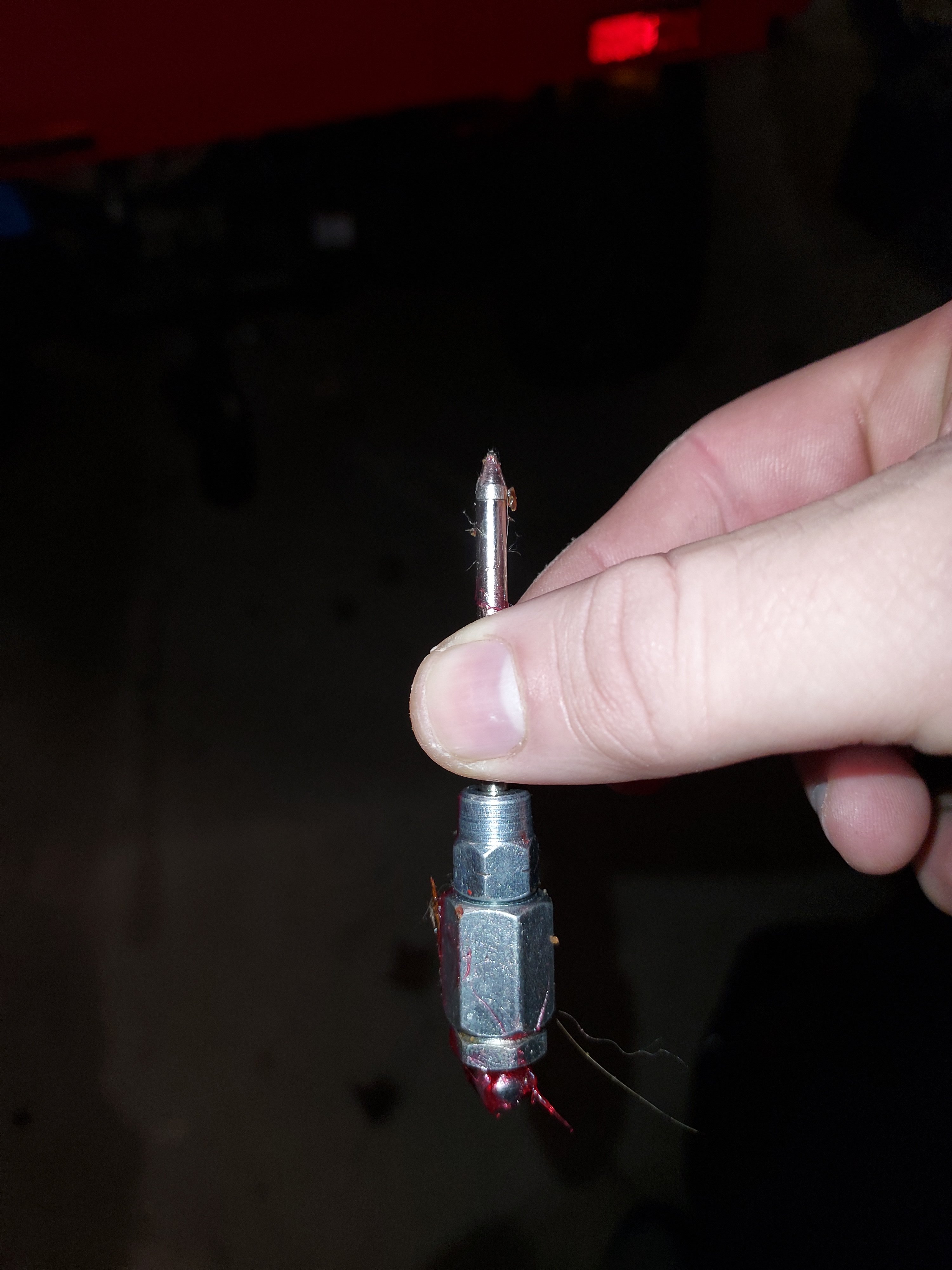
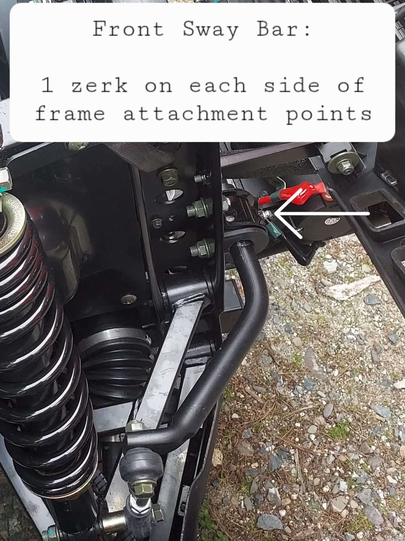
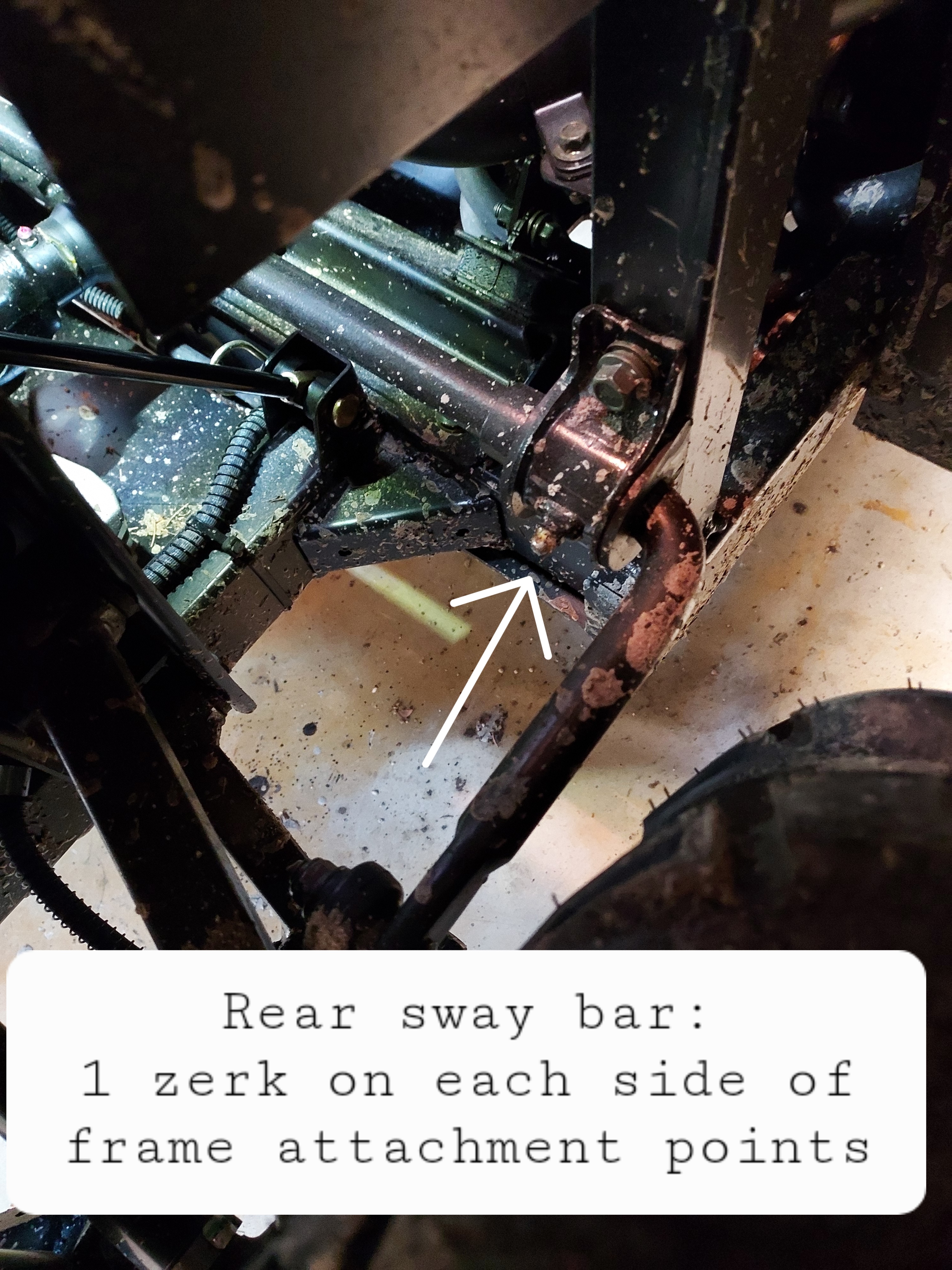
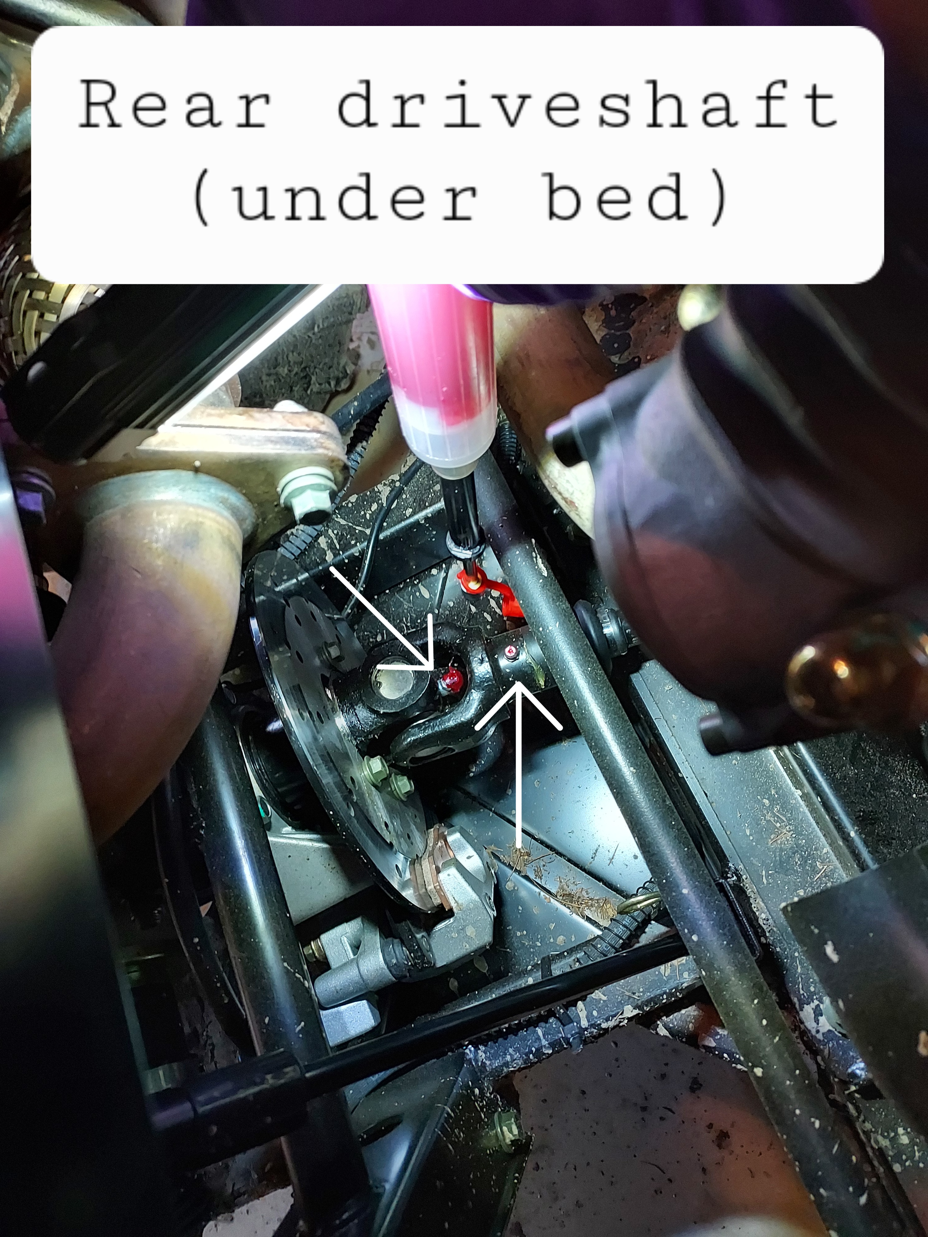
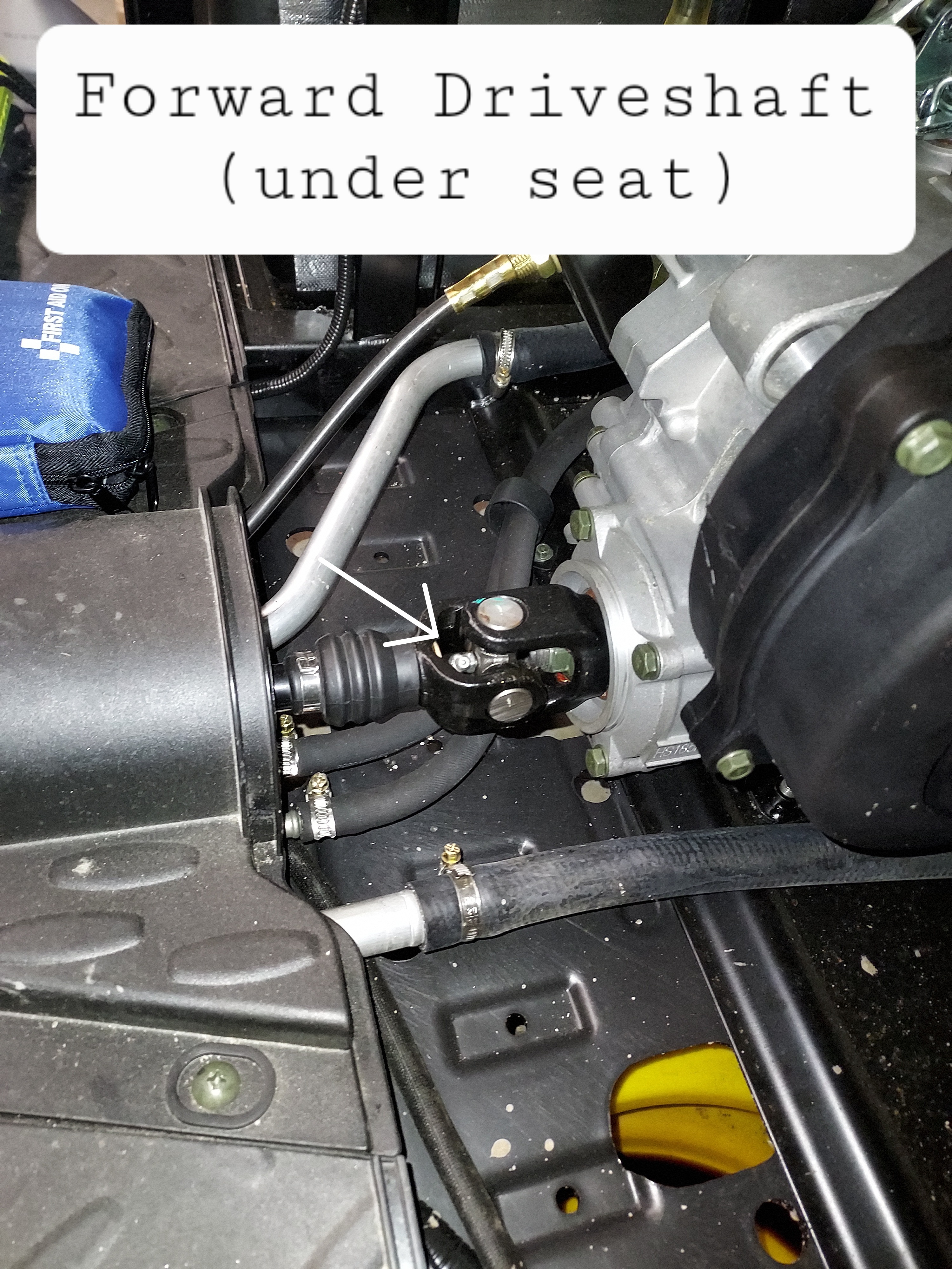
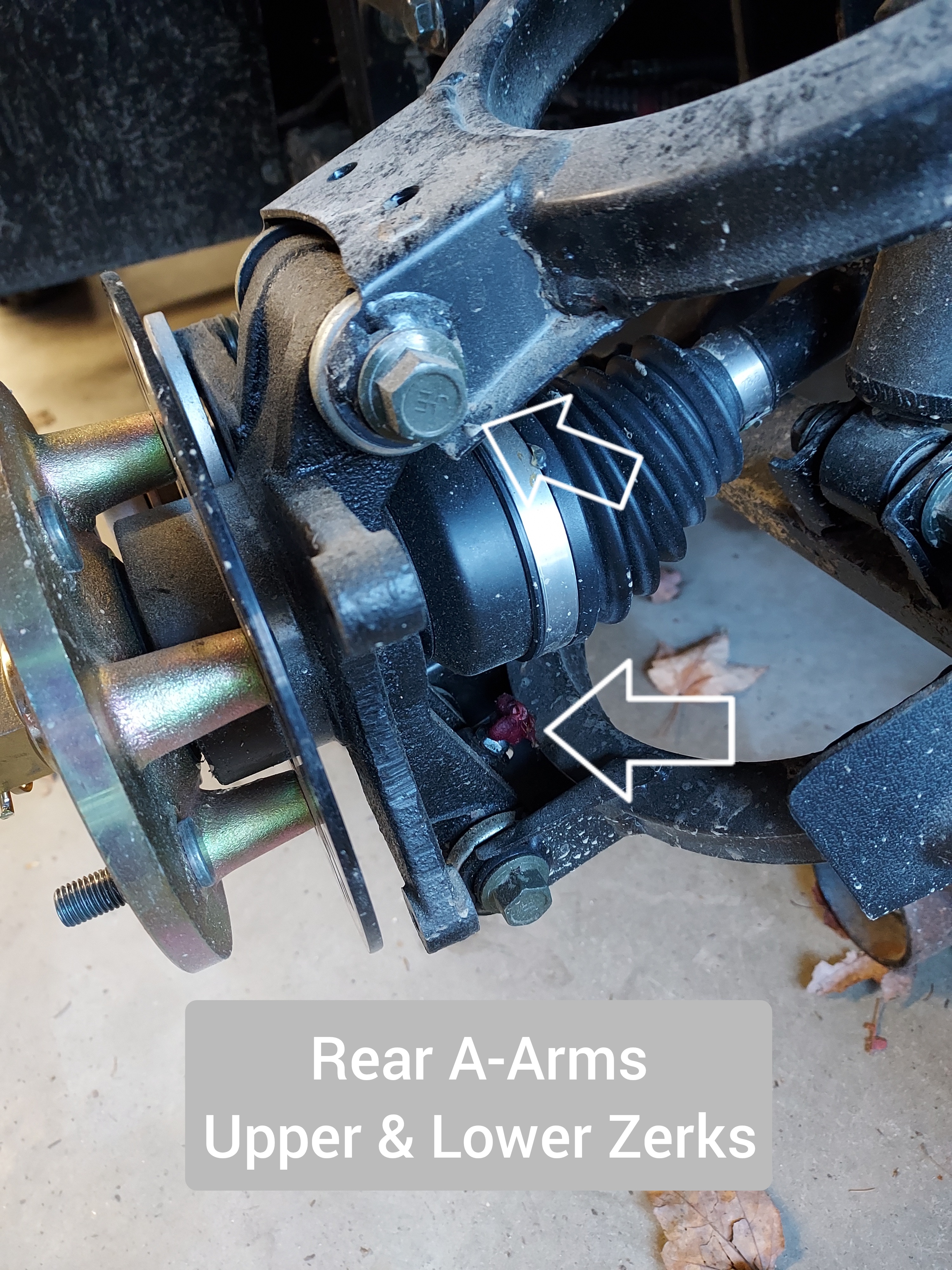
I've seen a number of requests for the location of all the grease points on these machines, and there is no definitive list in the manual. This covers the UT400, but other Coleman/Hisun models should be similar. Tools: First to grease your machine you need a grease gun and some NLGI#2 grease. You will find it helpful to buy a needle attachment as pictured here, due to poor clearance on some of the U-joints. The rest of the zerks use the standard attachment. Technique: Wipe any dirt/grease off the zerk before greasing to prevent pushing gunk inside and causing excess wear. Push the grease gun on the zerk at a straight angle and give it a few pumps. You will hear an oozing noise or sea grease coming out from the outside of the greased area when you've put enough grease in, a few pumps should be plenty. If it's just oozing around the zerk you either don't have a good seat with the gun, or the zerk may be rusted and the check ball frozen. Try seating it again and regrease. Wipe up any excess grease when youre done to prevent making a mess. Greasepoints: Rear A-Arms are greasable with the wheels on from the rear, I took the picture with the wheel off for easier visibility That's it. All other Hisuns should be substantially similar.

-
View File Hisun HS400/Coleman UT400 Parts Diagrams Compiled document with parts diagrams for Hisun HS400/Coleman UT400 for help in repairs where the service manual diagrams are poor or non existent. Submitter aefron88 Submitted 04/15/2024 Category Hisun
-

7 downloads
Compiled document with parts diagrams for Hisun HS400/Coleman UT400 for help in repairs where the service manual diagrams are poor or non existent. -
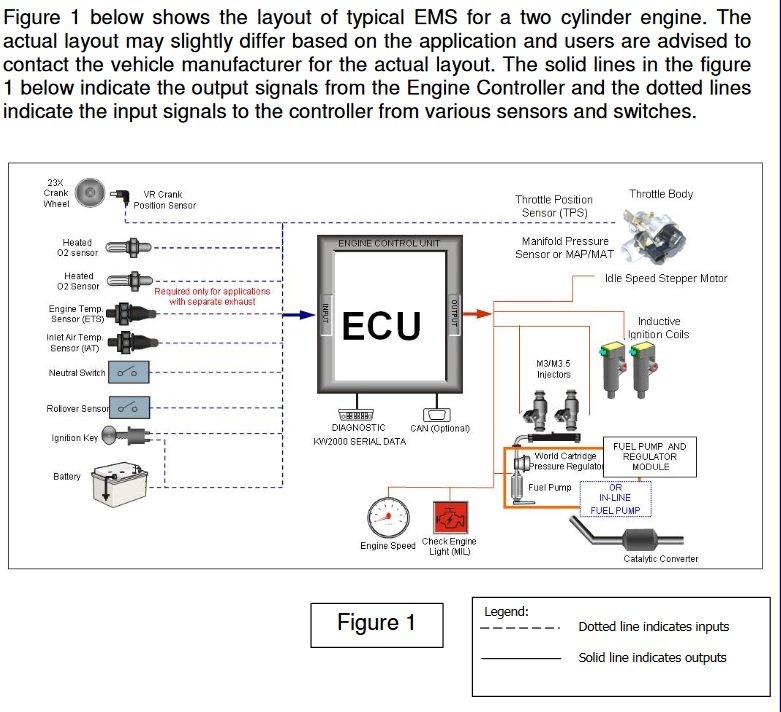
This post will explain how to hook up your PC to the ECU of a Hisun/Coleman/Etc UTV to be able to read error codes & engine parameters for troubleshooting purposes. This is applicable to all small engines using the Delphi MT-05 ECU. This should cover all fuel injected Hisun models, as well as various other Chinese FI engines, as the Delphi MT-05 ECU seems to be the favored ECU solution. Even though we get actual engine error codes to display on the dash, sometimes we have “pending codes” (not yet confirmed by the ECU) or other intermittent issues that are hard to diagnose, for example a poorly connected sensor that may give intermittent false readings, or a sensor that’s putting out bad date, but not bad enough for the ECU to realize. The setup requires 2 cables, which are available for around $25 combined, a PC with a USB port, and some charityware software called “HUD ECU Hacker”. This gives the same functionality as the $300 dealer code scanner for a fraction of the price. In searching I found info about HUD ECU Hacker, but I have yet to see info anywhere about how to hook it up to a Hisun, so I took the leap and bought some cables, and made it work. I will show a step by step of how to do so in post two. I will be breaking this down into 2 posts: Delphi ECU Info & Overview (This post) System setup & use Delphi ECU Info (Skip ahead to the next post if your eyes glaze over technical details) The Delphi MT-05 ECU was developed to allow small engines to use fuel injection. A fuel injection system requires feedback from various sensors to operate efficiently. This feedback allows the adjustment of ignition timing, fuel injection volume, etc to efficiently and cleanly produce the most power possible from a given engine. The MT-05 ECU has a number of sensors that are required for proper functioning including; Coolant temp, crankshaft position, intake temp, intake pressure, exhaust O2, throttle position, as well as some other optional sensors that are used on more complex vehicles. From the sensors the ECU adjusts: Fuel injector timing/pulse, Idle air control valve, and ignition coil The Delphi MT-05 puts out diagnostic data, however it is not ODB2 like a modern car, where is where it gets tricky reading it. There are three options, there is an old 16 bit piece of software Delphi has that is not able to run on a modern computer, there is the motorscanner tool for dealers ($300), or there is freeware HUD ECU Hacker with the proper cables.
-
Can someone explain why the master link i got from an atv shop wont work on the chain for the strike 250? It looks like it fits but its just thick enough its wont slip through the holes of each end of the link! The chains says its a 520 link and thats what i got but i am wondering if the hisun chain is just a hair different.
-
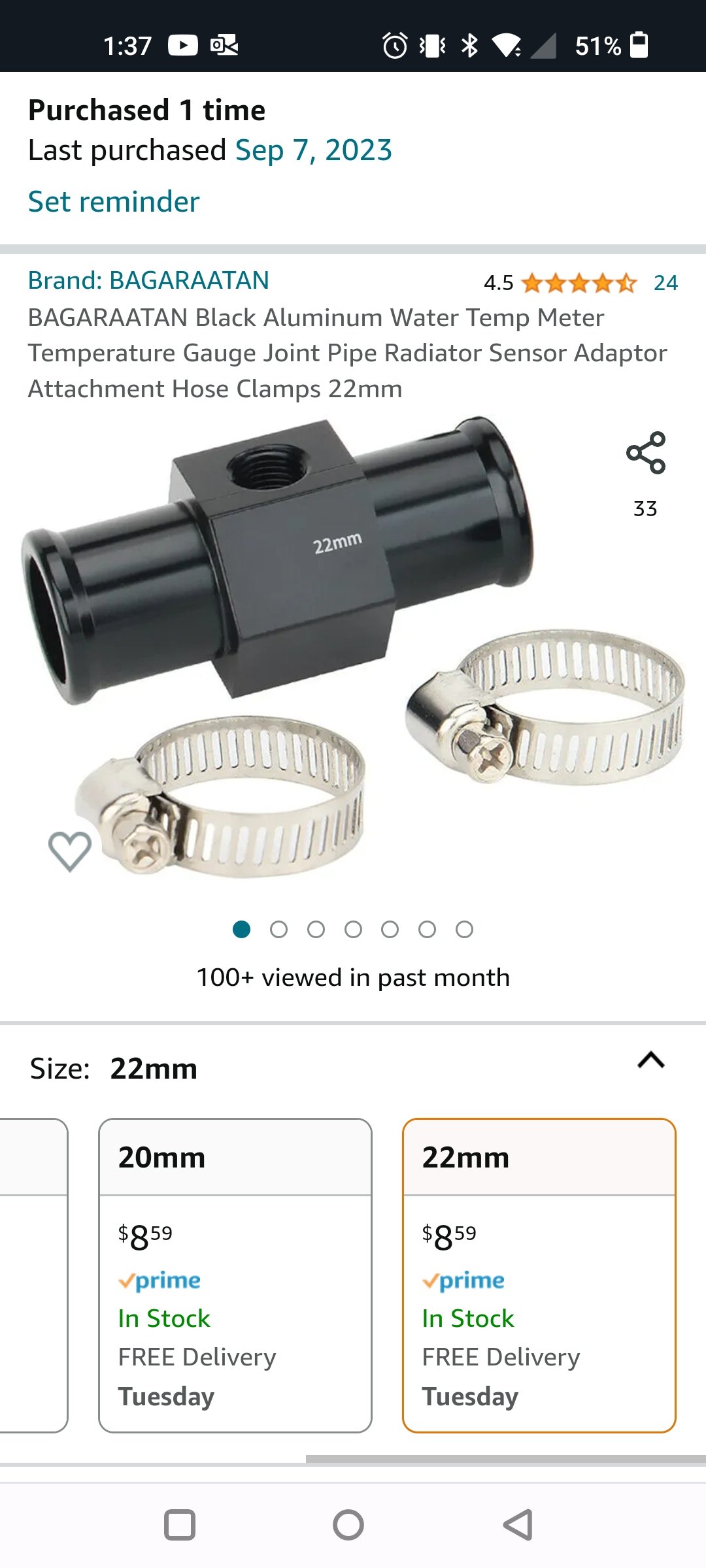
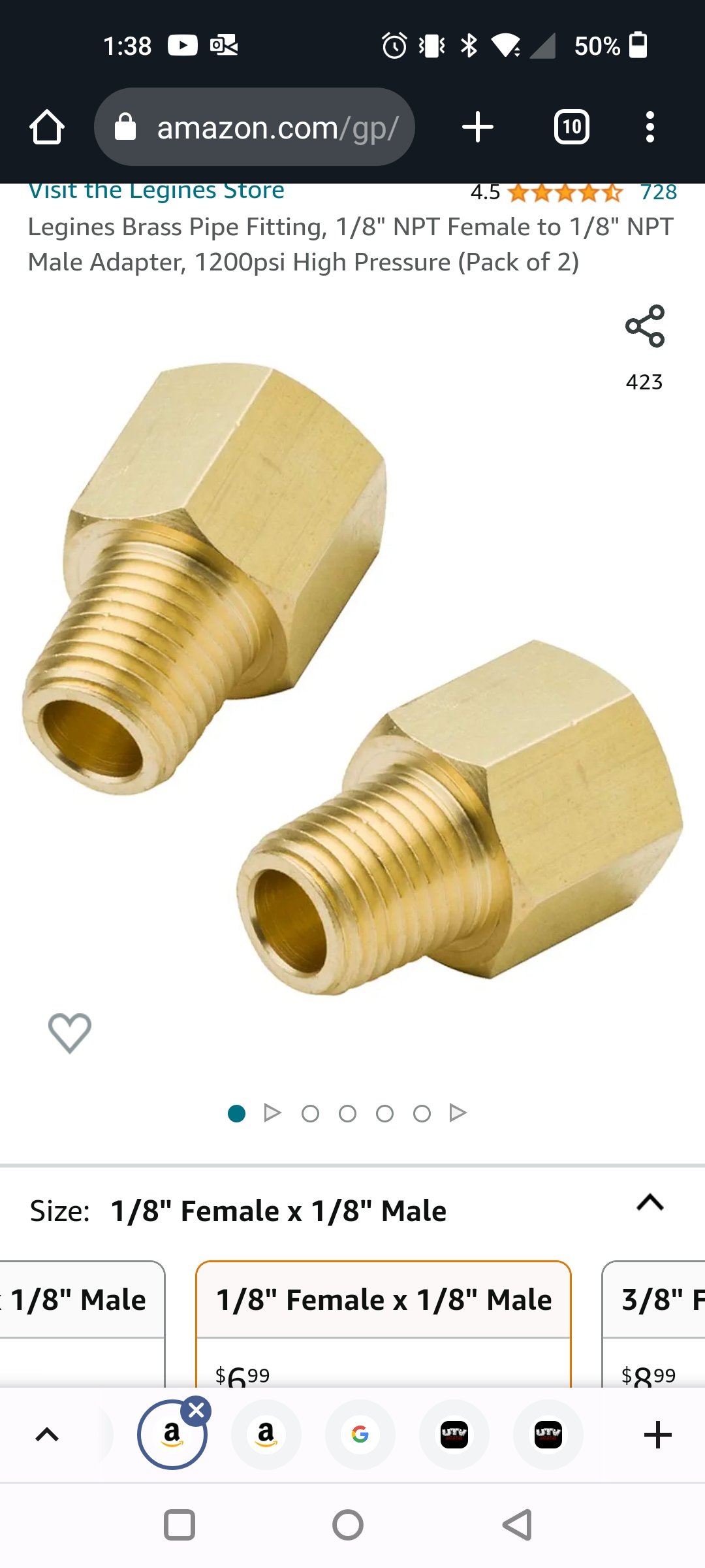
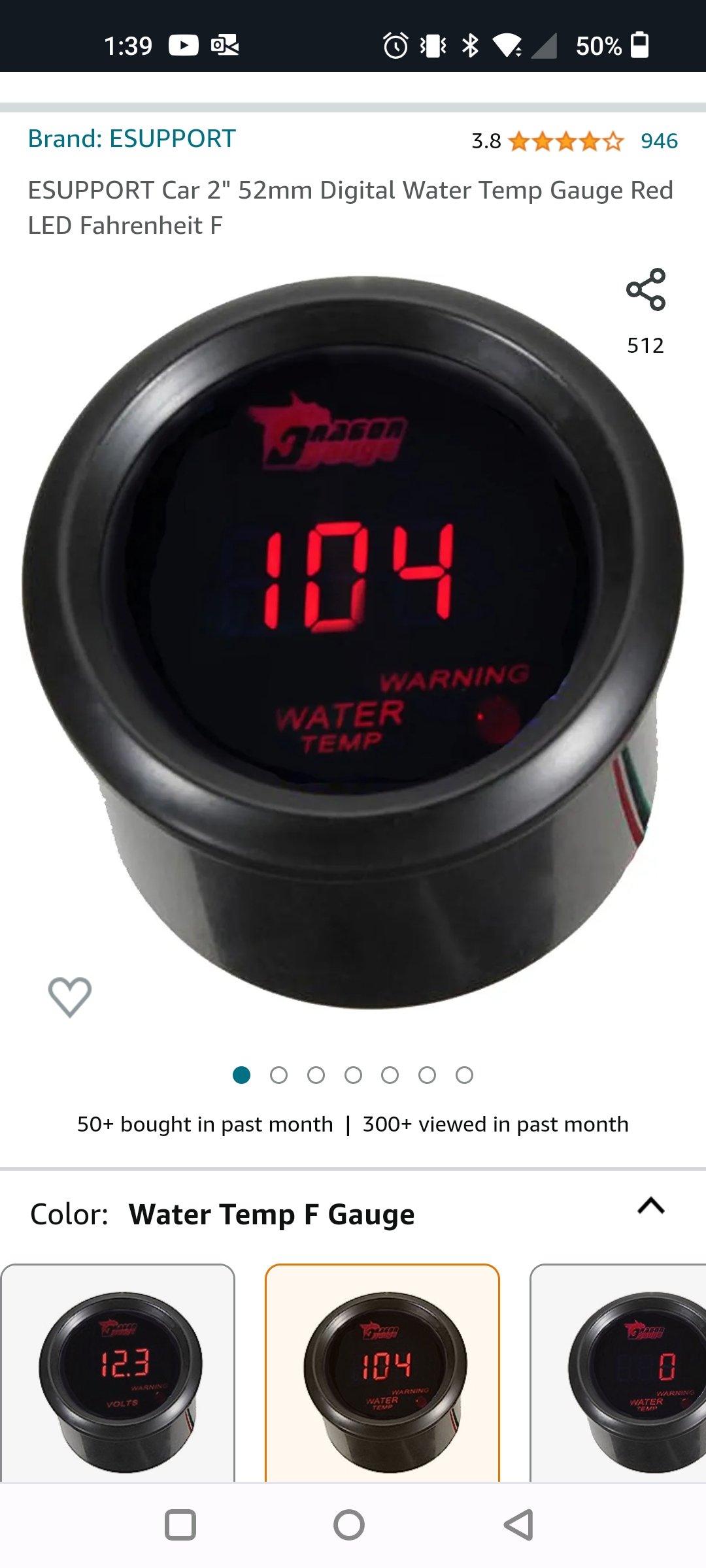
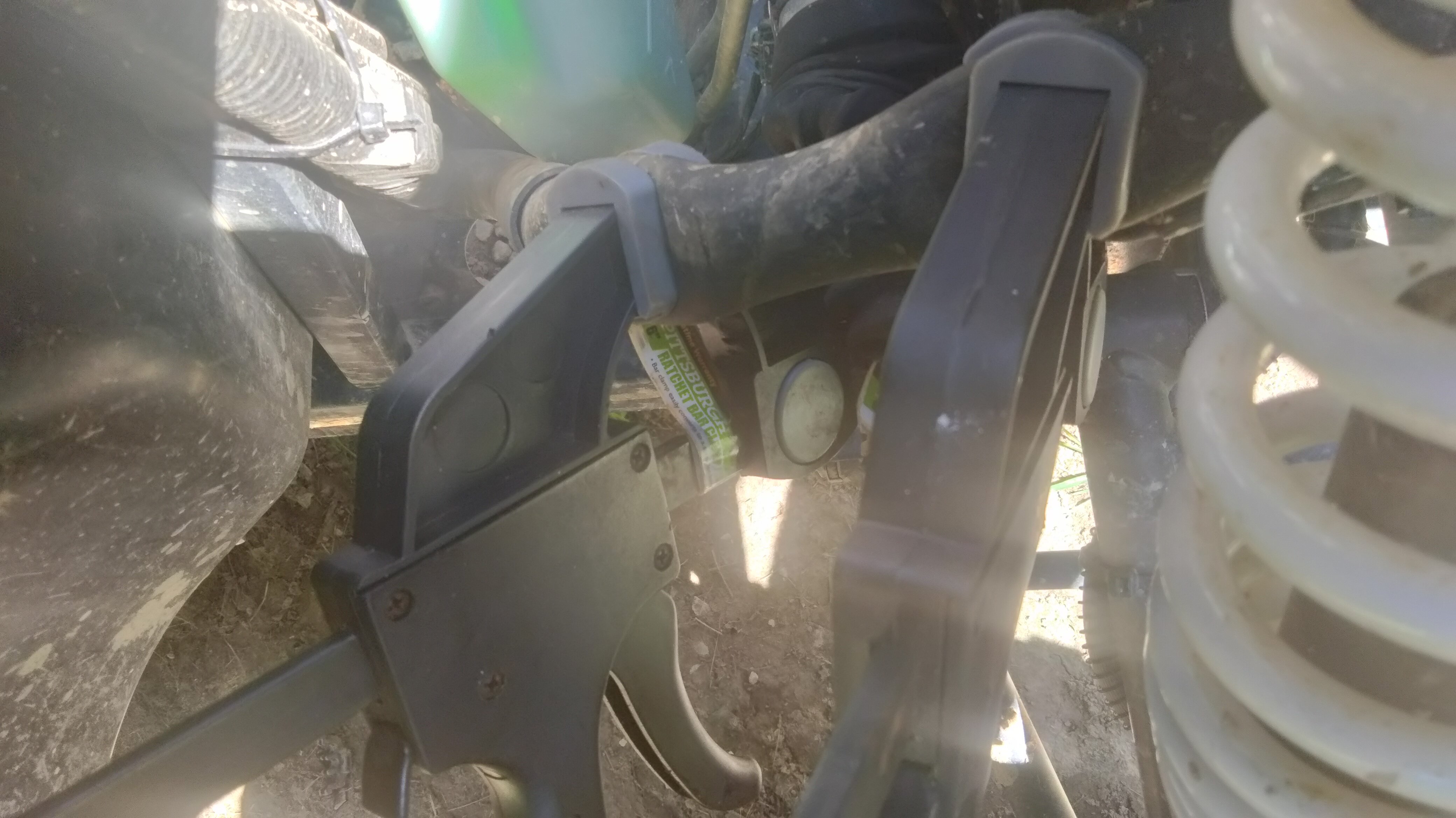
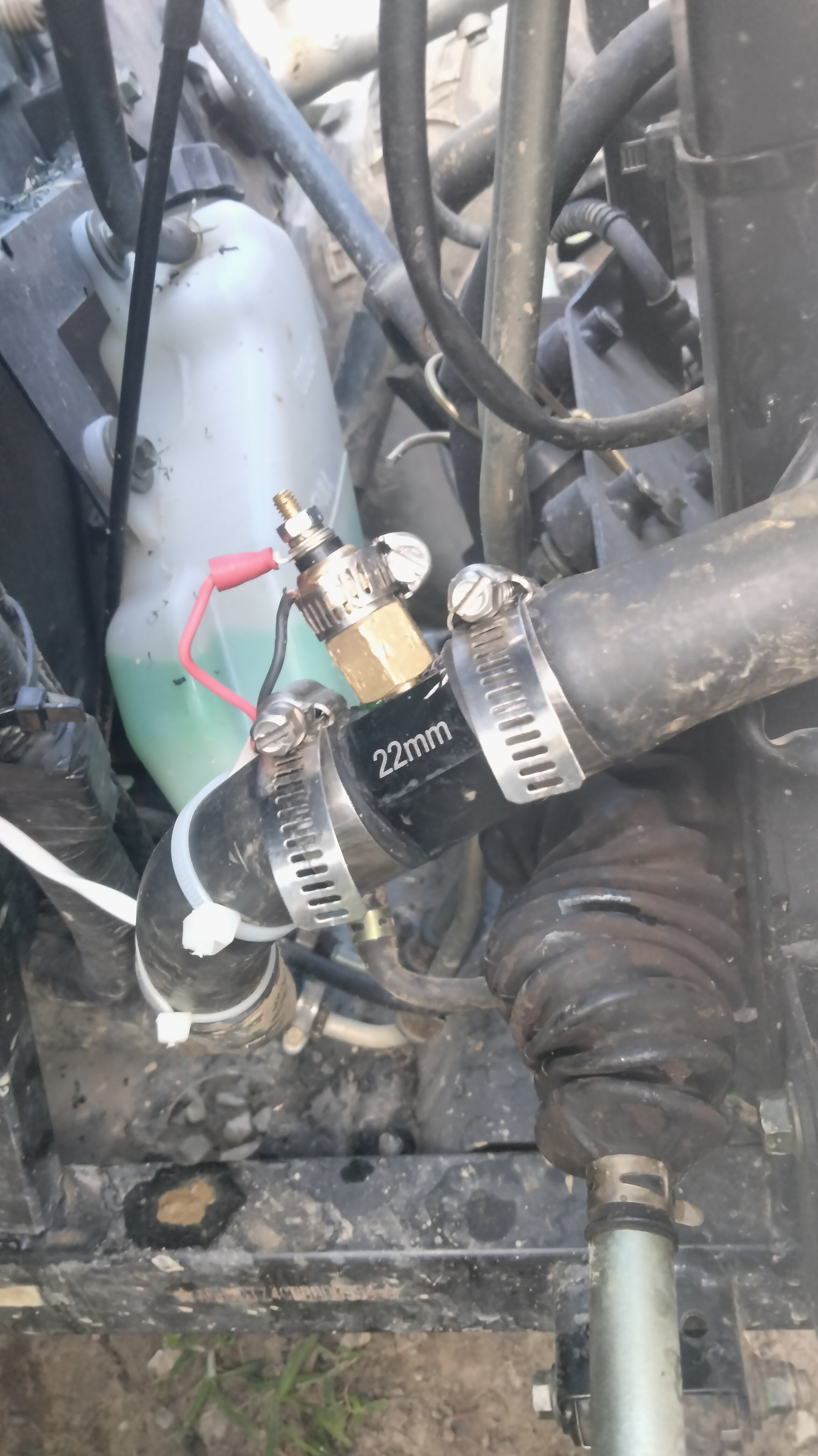
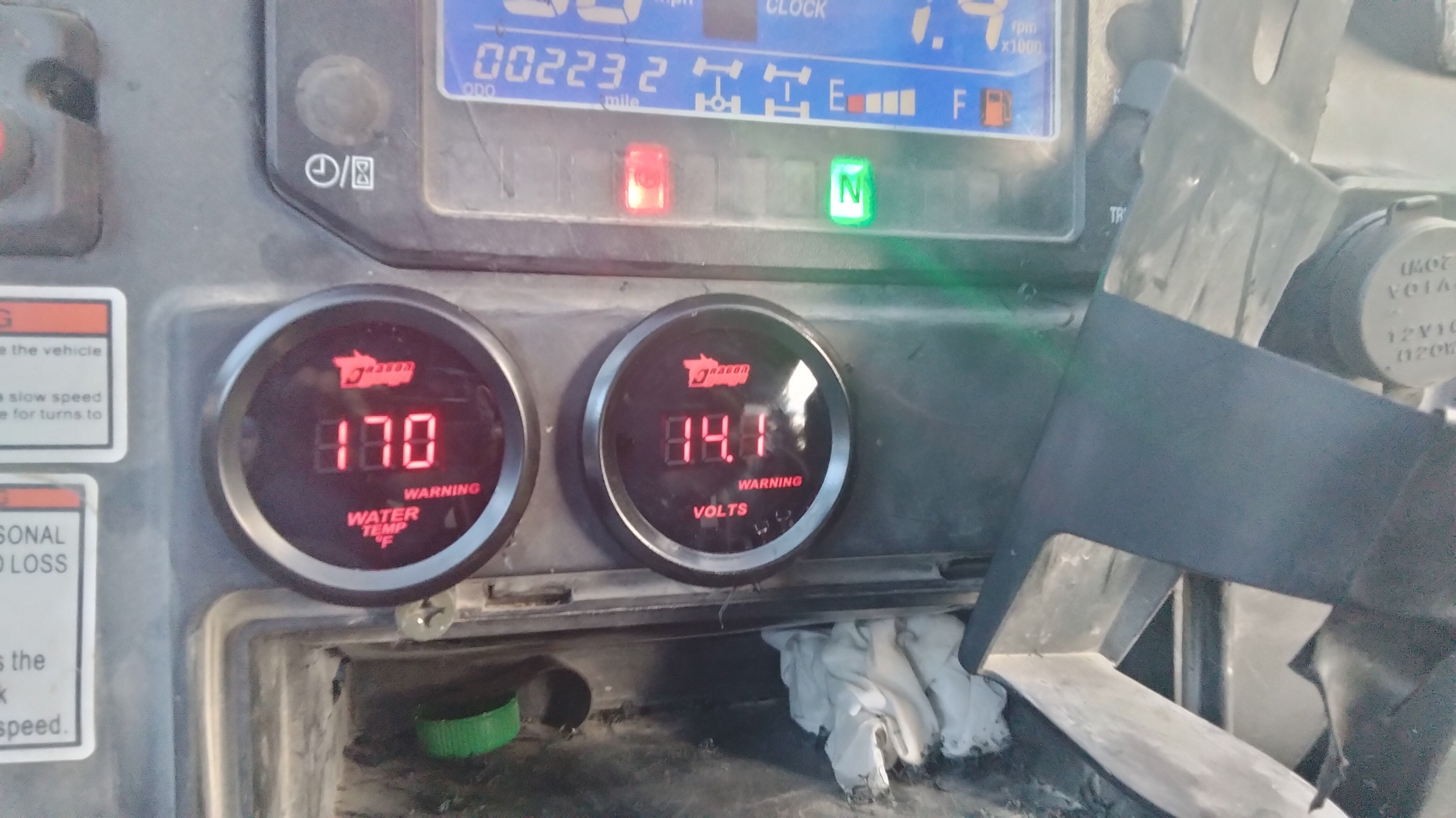
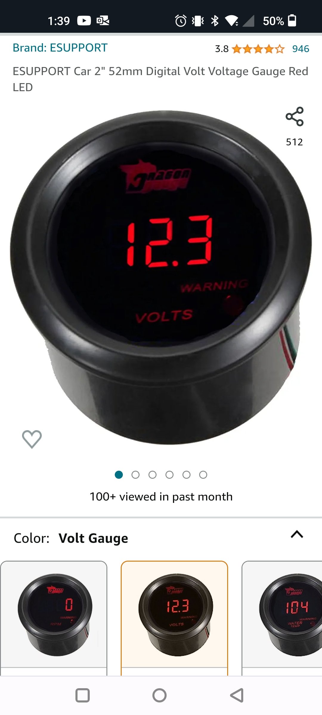
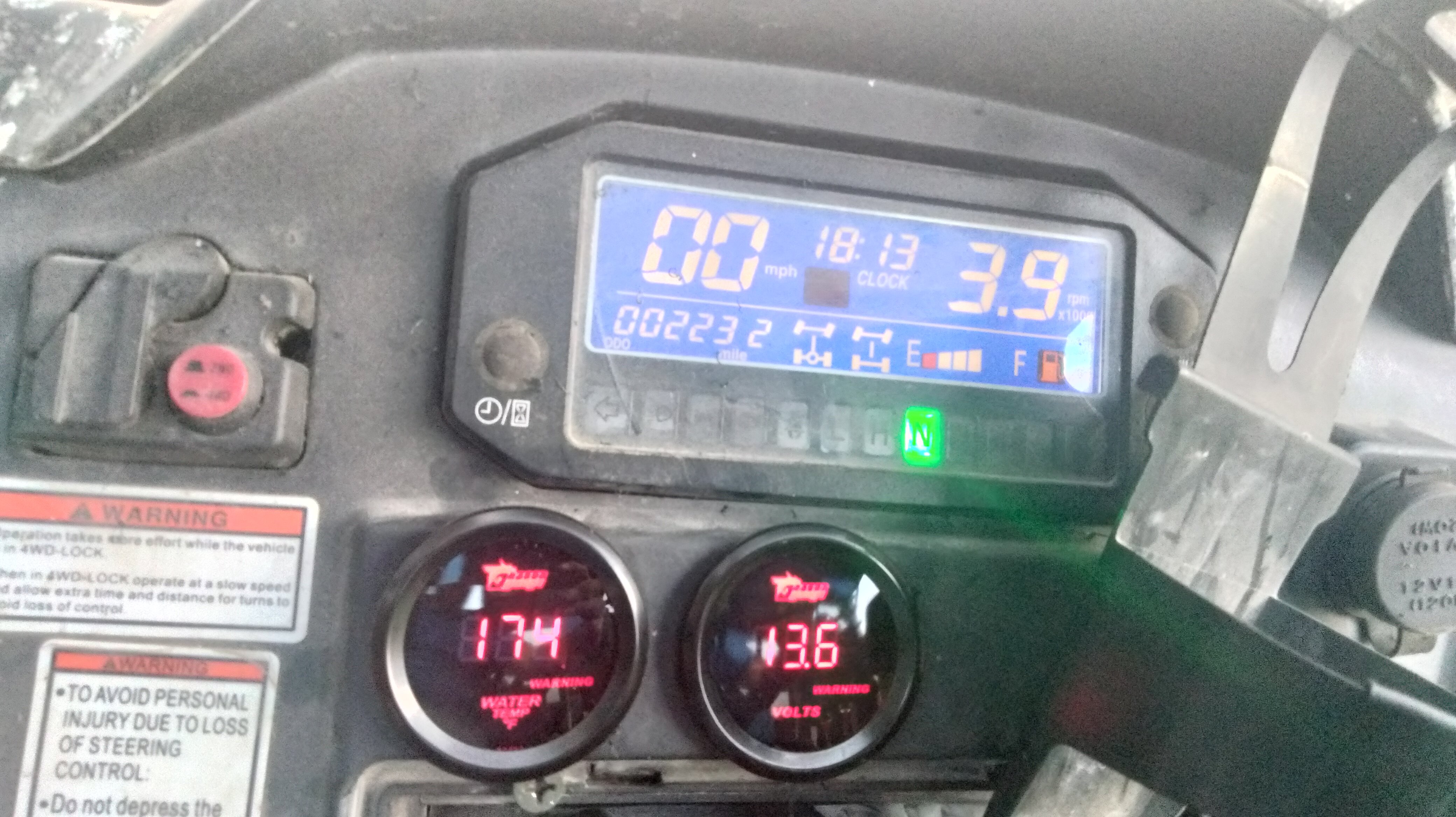
 I installed an electric coolant temp gauge and volt gauge today. The oil pressure gauge I ordered had a bad sending unit. So once the replacement arrives. I'll add that install to the post. The I used a 22mm temp radiator adapter. 1/8 " NTP x 1/8 NTP adapter. And an electric temp gauge. Had to take a drill and drill bit to enlarge the 1/8 NTP adapter to allow the temp sending unit to pass thru. Another user on the forum enlarged the 1/8 NTP hole in the 22mm radiator to 1/4 NTP and used a 1/4 NTP x 1/8 NTP reducer. Either way would work. Both has it challenges. And both accomplished the same thing. To get the sending unit just barely in the coolant. If you just put the sending unit in. IMO it just blocks too much of the coolant flow. I didn't get a pic of how far the sending unit protrudes into the rad adapter. But it wasn't a lot. And also since it an electric gauge the sending unit needed to be grounded. But since there wasn't a place on the temp radiator adapter. I used a clamp to secure a ground/negative wires to the temp sending unit. The gauge wiring was simple. The gauge's wiring harness had a red, green, and black wire. Red goes to a positive. Black to a negative. Green to the sending unit. Since I had some 18 AGW speaker wire. I used that to run to the sending unit. Red to green, black to black. Then another piece of the speaker wire from the gauge to power source. I tapped into the 12V power outlet on the dash. (Just as I did for the overhead fan.) Then used a 2" hole saw to cut into the plastic above what I'd call the radio door. The gauge goes to about 174° F then the radiator fan kicks on. Cools down to about 150° F and kicks off. Now the lowest the temp gauge will read is 104° when you first start the machine. That is the nature of the gauge. Even says so on the web page. So I'll just have to live with it. The voltage gauge . Was simple to install. Just a positive and negative wire to connect. Tapped into the 12V power outlet on the dash.
-
I installed an electric coolant temp gauge and volt gauge today. The oil pressure gauge I ordered had a bad sending unit. So once the replacement arrives. I'll add that install to the post. The I used a 22mm temp radiator adapter. 1/8 " NTP x 1/8 NTP adapter. And an electric temp gauge. Had to take a drill and drill bit to enlarge the 1/8 NTP adapter to allow the temp sending unit to pass thru. Another user on the forum enlarged the 1/8 NTP hole in the 22mm radiator to 1/4 NTP and used a 1/4 NTP x 1/8 NTP reducer. Either way would work. Both has it challenges. And both accomplished the same thing. To get the sending unit just barely in the coolant. If you just put the sending unit in. IMO it just blocks too much of the coolant flow. I didn't get a pic of how far the sending unit protrudes into the rad adapter. But it wasn't a lot. And also since it an electric gauge the sending unit needed to be grounded. But since there wasn't a place on the temp radiator adapter. I used a clamp to secure a ground/negative wires to the temp sending unit. The gauge wiring was simple. The gauge's wiring harness had a red, green, and black wire. Red goes to a positive. Black to a negative. Green to the sending unit. Since I had some 18 AGW speaker wire. I used that to run to the sending unit. Red to green, black to black. Then another piece of the speaker wire from the gauge to power source. I tapped into the 12V power outlet on the dash. (Just as I did for the overhead fan.) Then used a 2" hole saw to cut into the plastic above what I'd call the radio door. The gauge goes to about 174° F then the radiator fan kicks on. Cools down to about 150° F and kicks off. Now the lowest the temp gauge will read is 104° when you first start the machine. That is the nature of the gauge. Even says so on the web page. So I'll just have to live with it. The voltage gauge . Was simple to install. Just a positive and negative wire to connect. Tapped into the 12V power outlet on the dash.
-
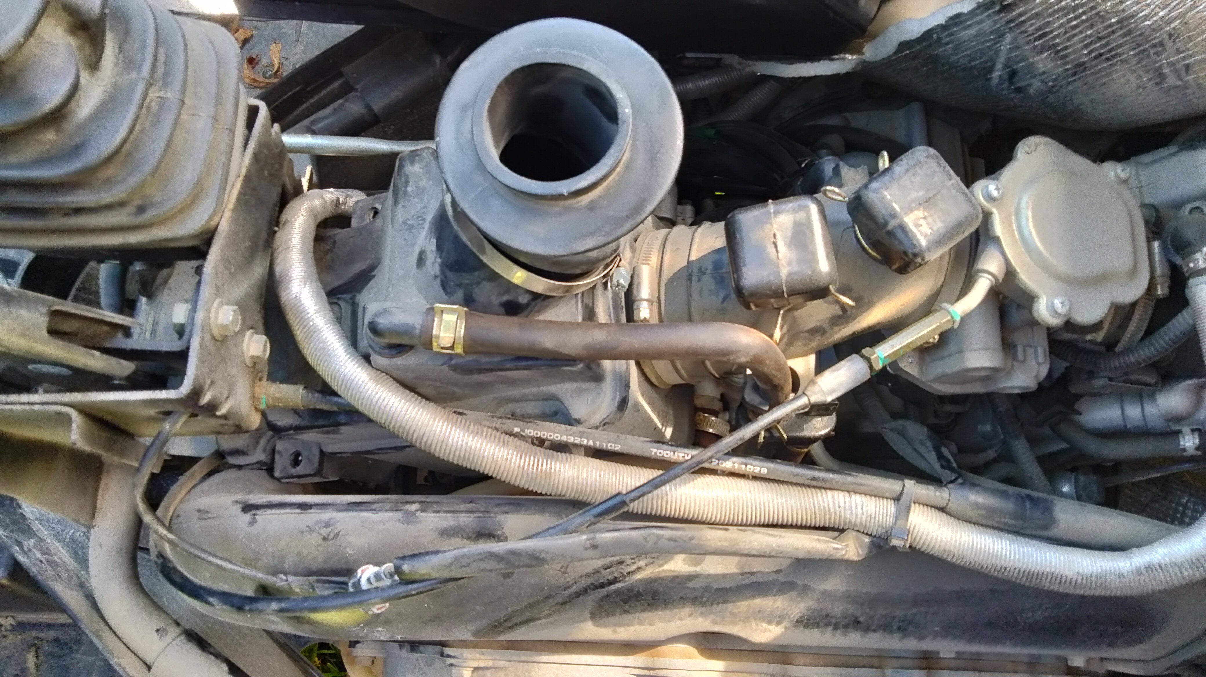
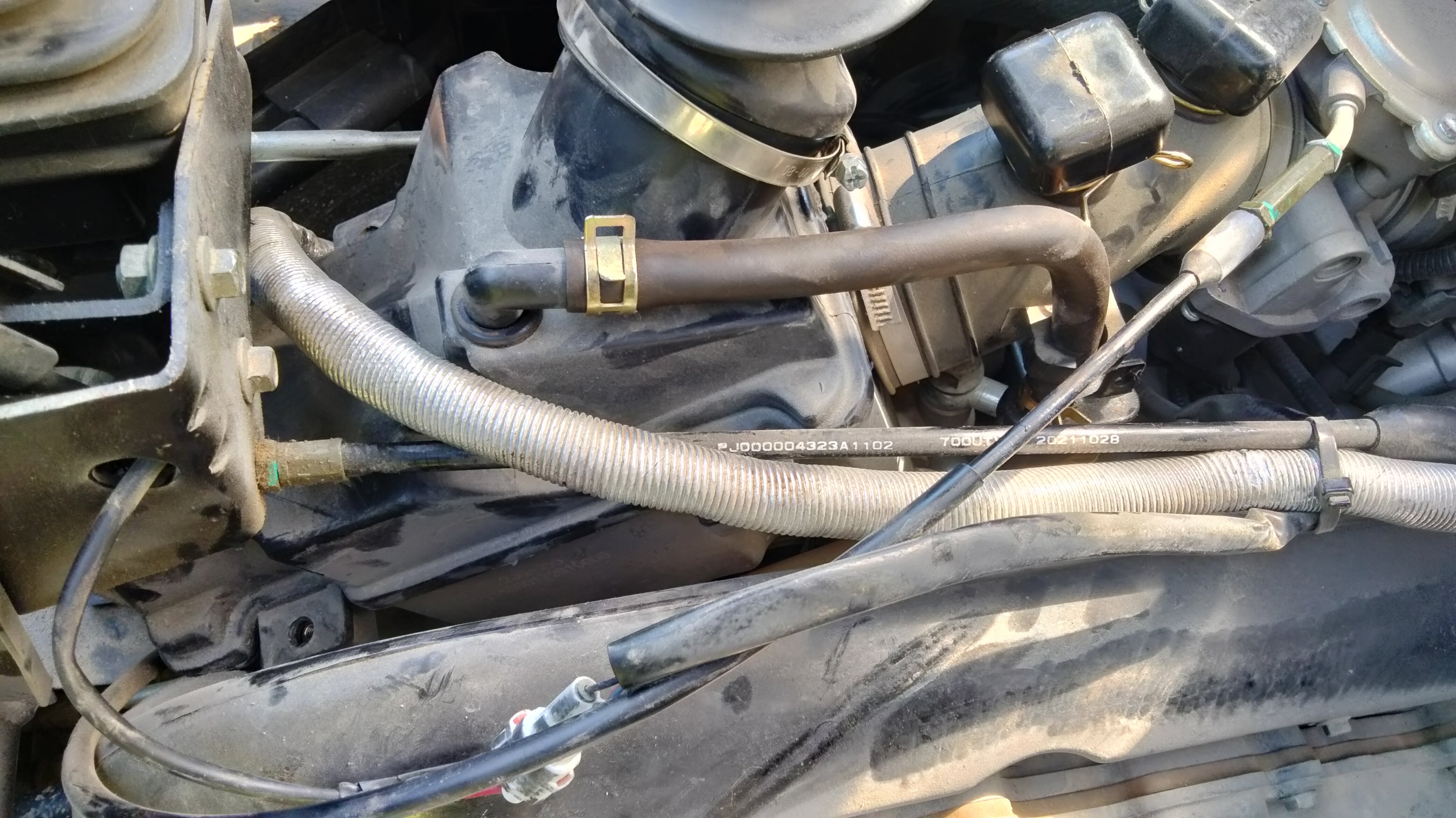
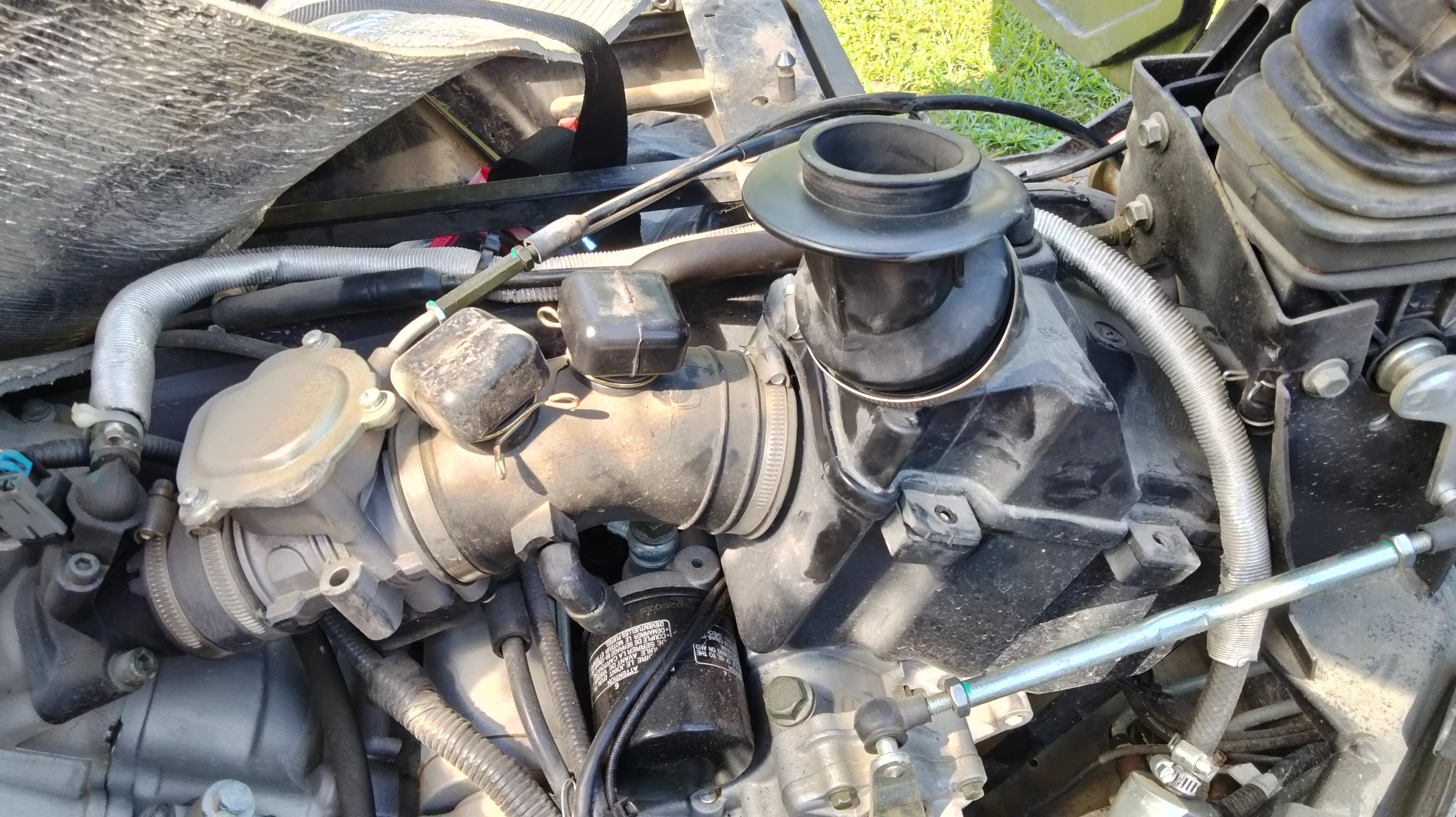
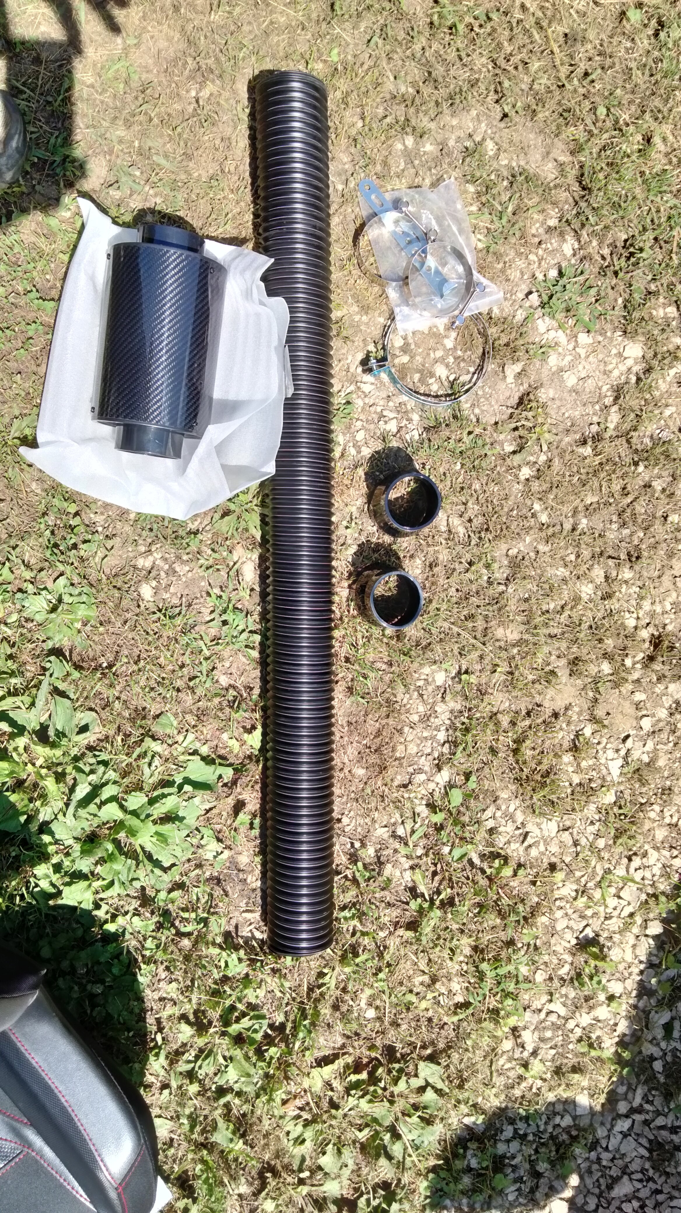
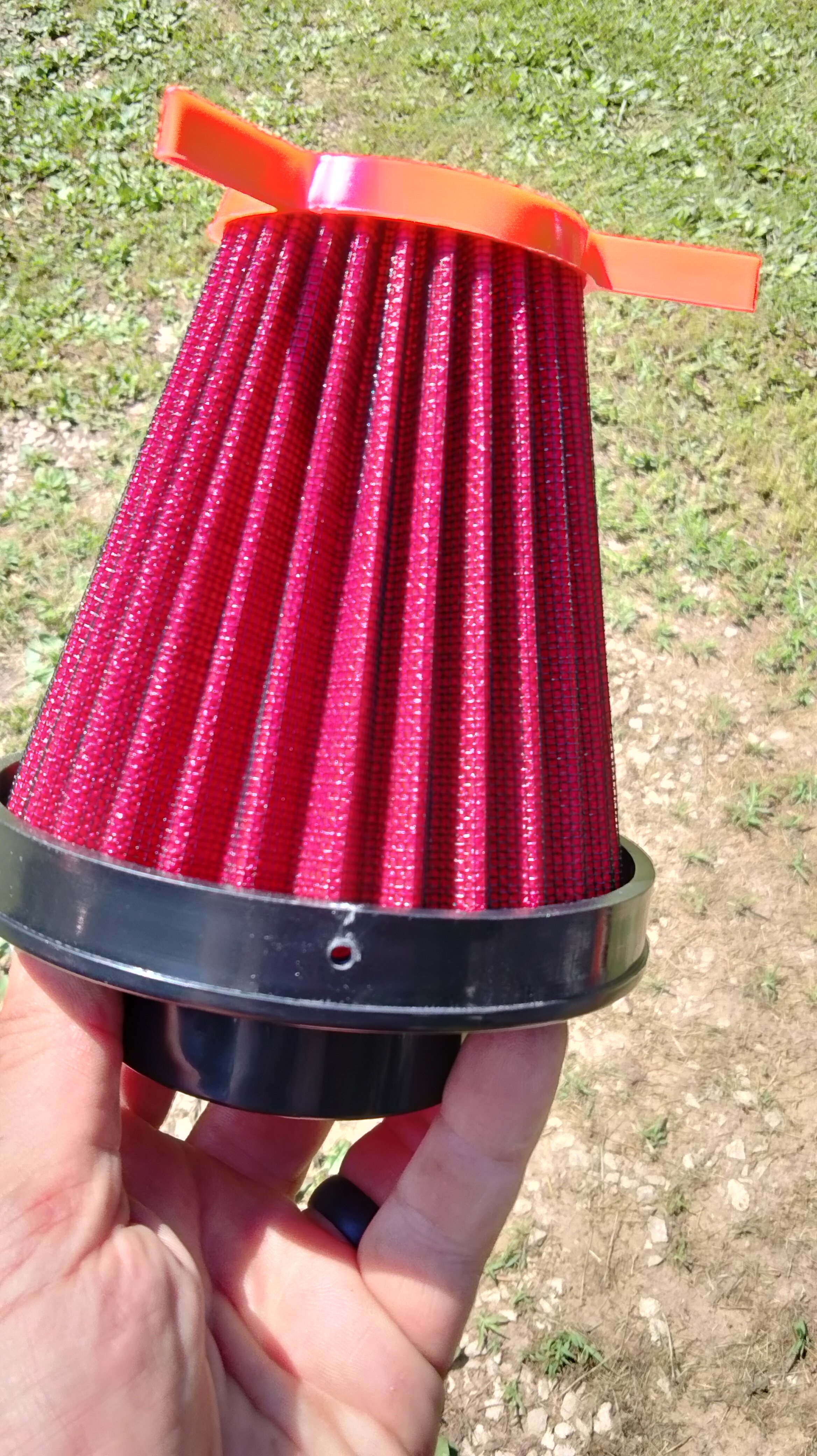
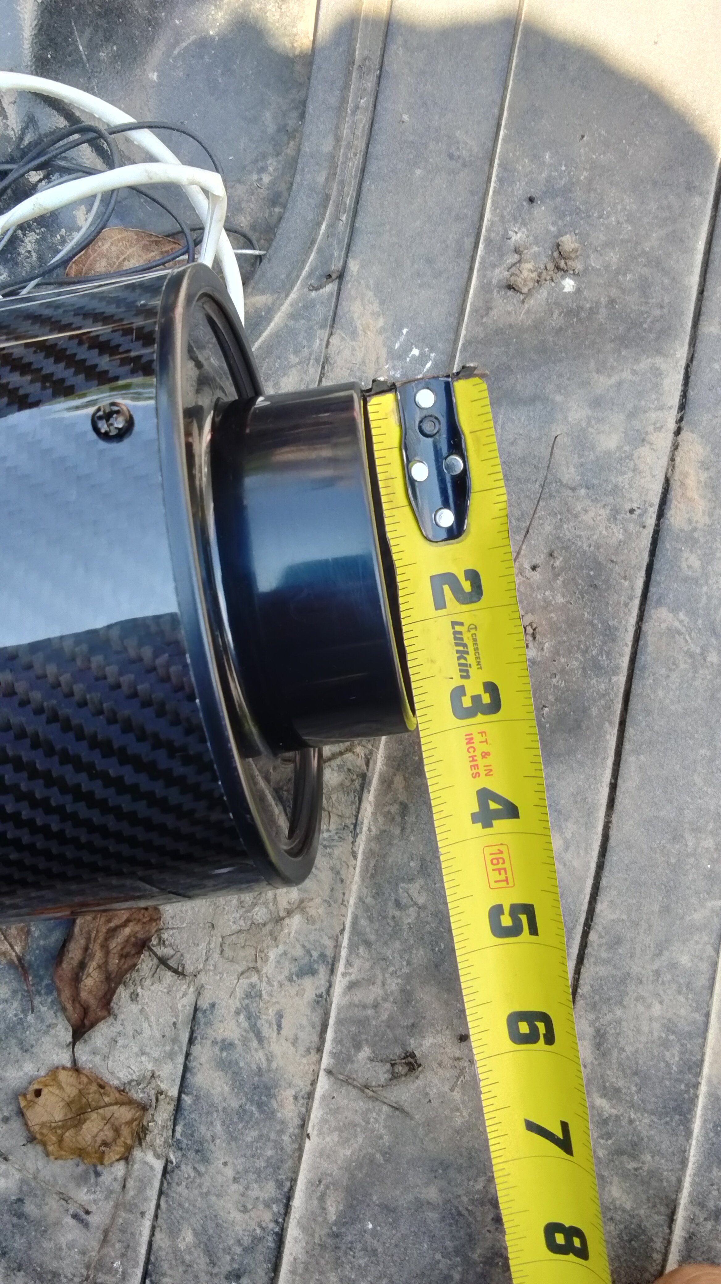
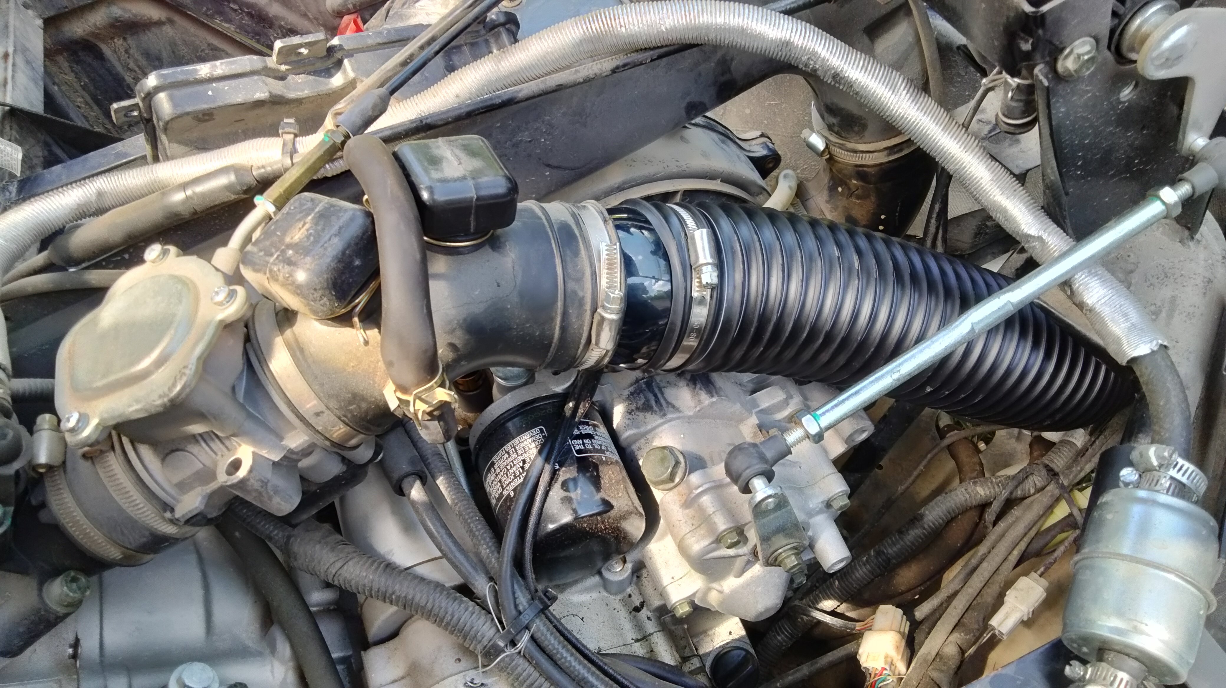
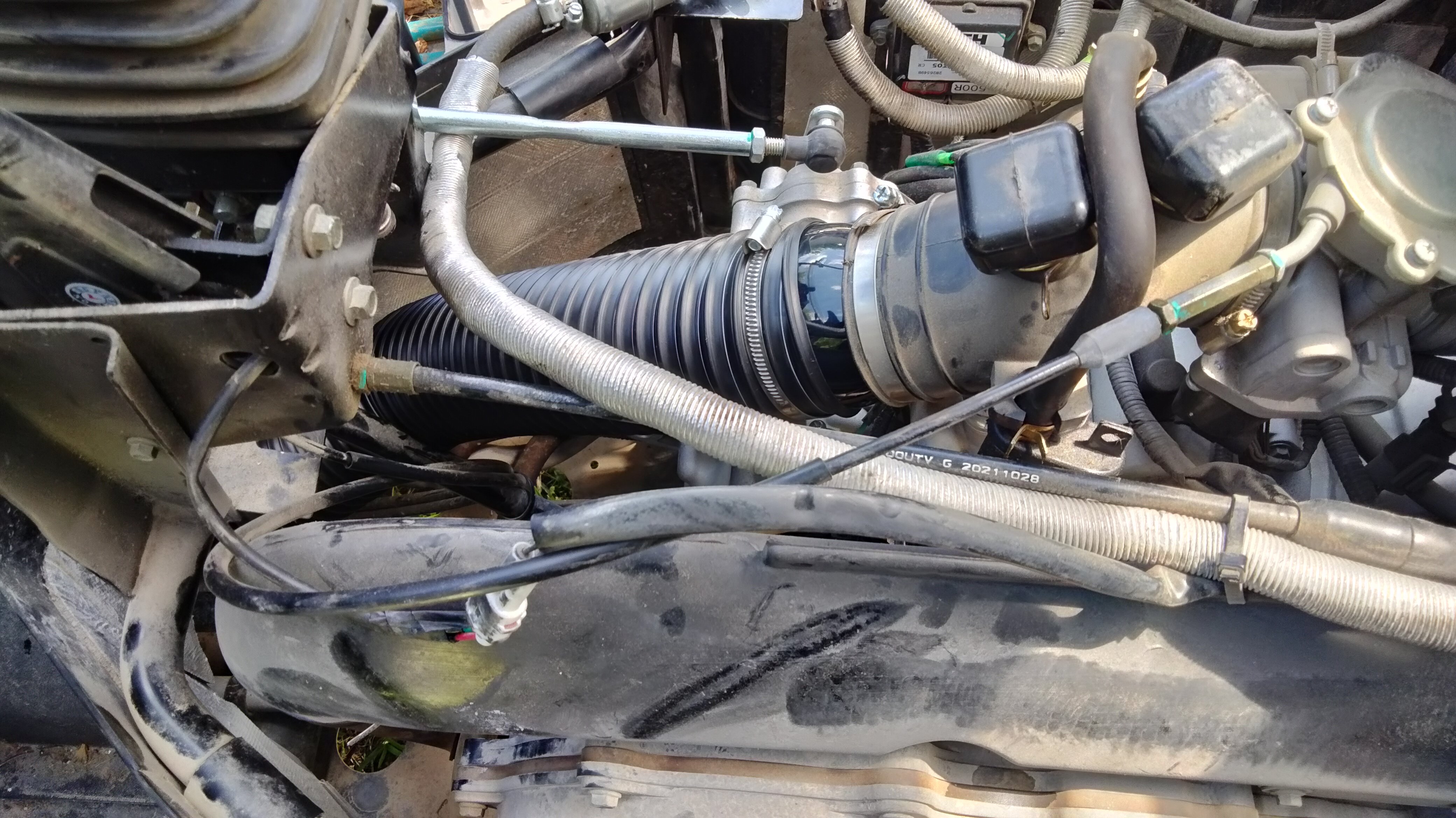
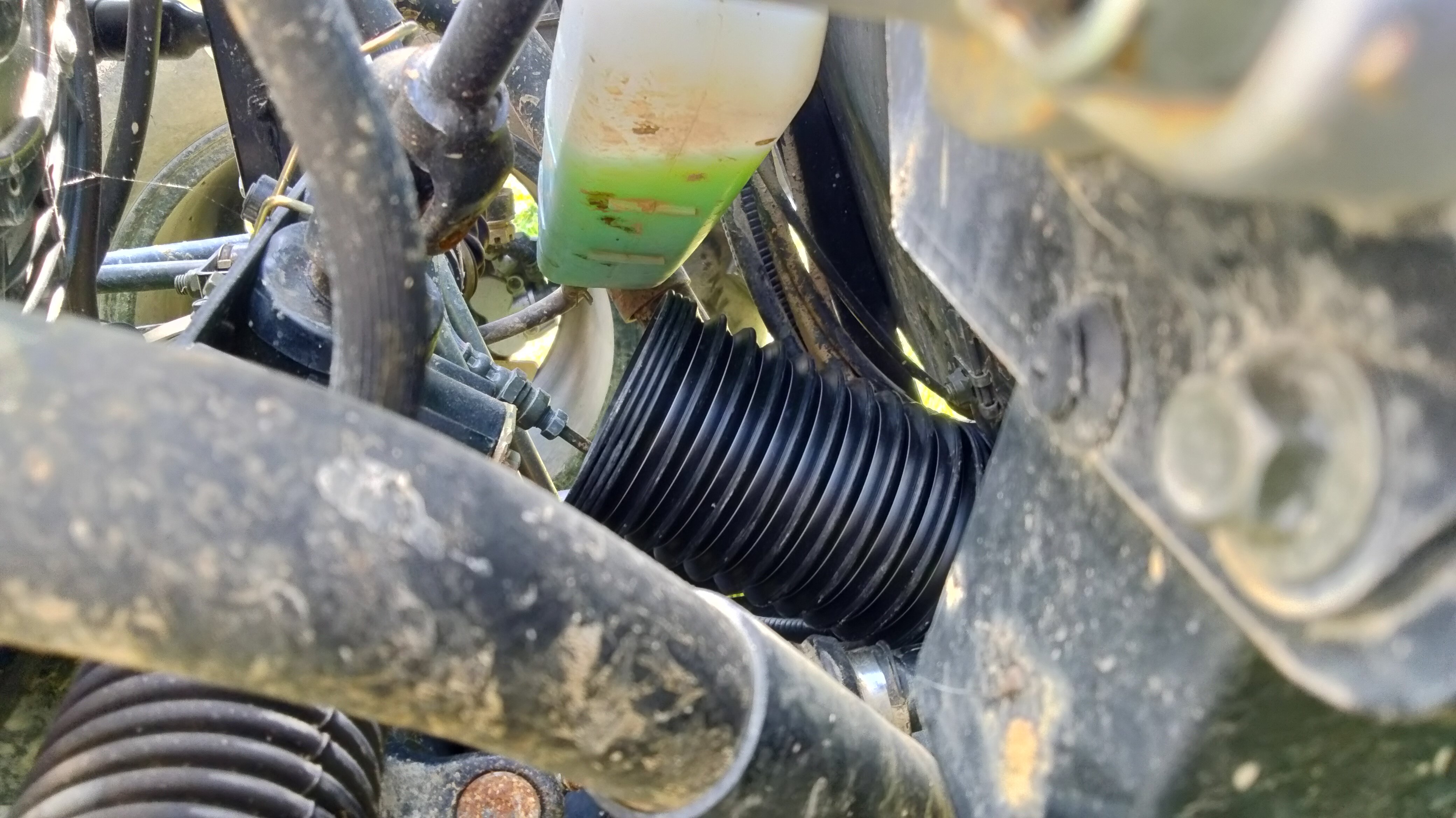
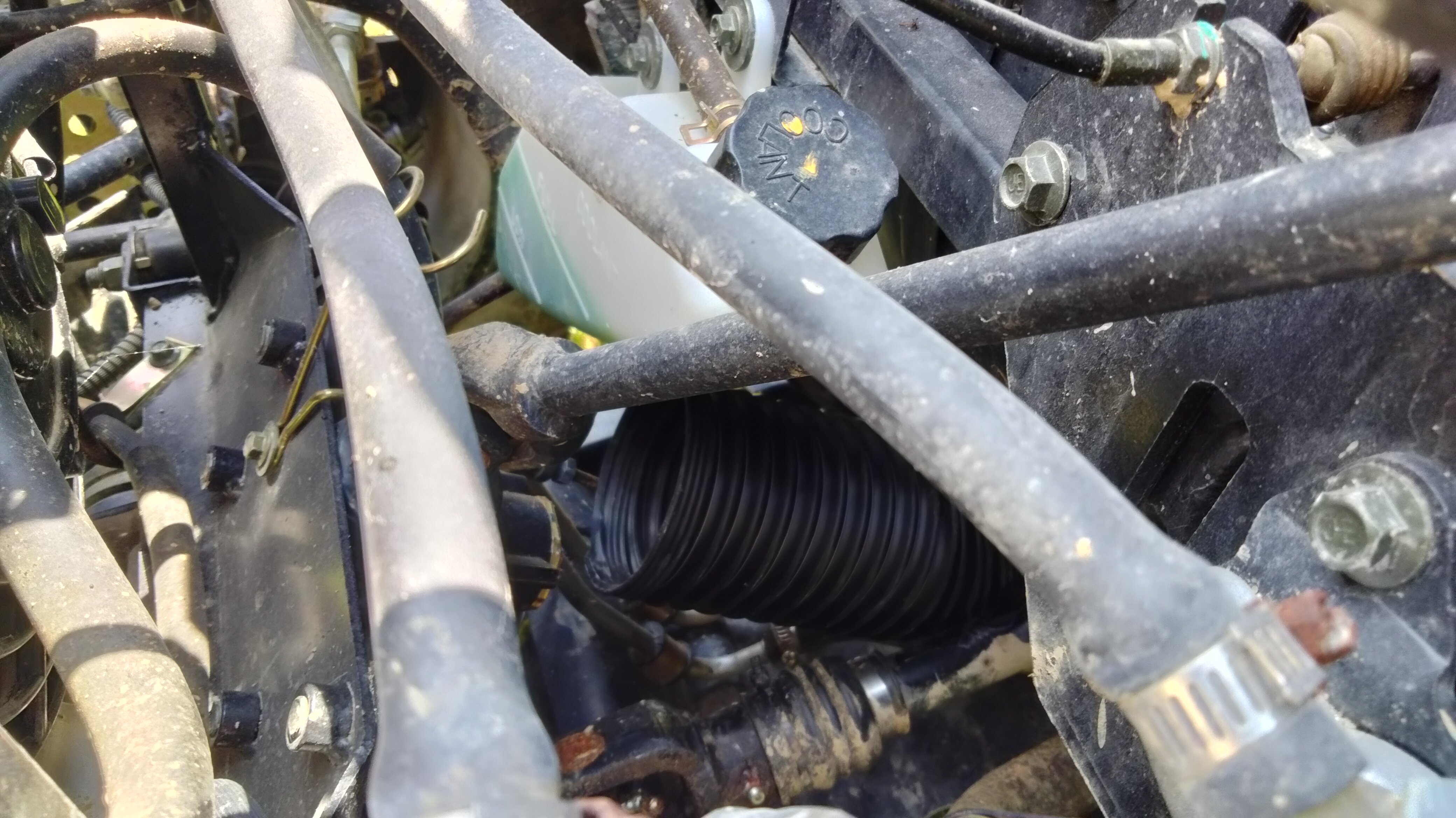
At 185 hours while do a little riding noticed using a little more fuel that the trip should have taken and running a little rough. Thought it might be time to clean the air filter. I while back, I bought a filter kit for another sxs I had but never installed. I was going to do the snorkel thing. Anyway, while I was as cleaning the air filter for the Axis 500. I mocked up this filter kit and wanted to know if anyone could give a reason why this wouldn't work. I plan on removing the air box completely. Moving the PCV valve hose to the side of the large hose going to the throttle body instead of the way it is now. Now it connects to the air box. There is already a hole in that hose and it just has a 90° fitting on it and then a plug. Then route some pipe thru the tunnel that the front drive shaft uses. Then up under the hood and mount the new filter there. I even bought a hood scoop to use. See pics below. Here is the way it is from the factory. Notice the hose plugged into the top of the air box. That is for the PCV valve. It provides suction for the crankcase to keep from blowing seals. You can't see in the pic, but there is a hose that connects to the crank case. That hose connects to a box with 2 hoses coming off. One of those hoses goes down to under the sxs to let any oil that is sucked up drip on the ground. The other hose connects to the air box. Here is the passenger side of the air box. Notice the 90° nipple on the large hose running between the air box and the throttle body. Here is a pic of the kit I got off Amazon. Here are some pics with the air box removed, PCV hose relocated, and the hose coming up into the hood area thru the tunnel that the front drive shaft uses. I will probably have to relocate the radiator overflow jug. I know I will probably have to use solid pipe instead of that plastic flex stuff. And will have to keep it clear of the drive shaft. The only issue I see it the air coming in thru the PVC hose is not filtered. It also could cause more suction on the crankcase and cause the sxs to use some oil. Those little square boxes on top to the throttle hose are empty. I may have to connect the PCV hose to that and add a filter in that square box. But other than that. Does anyone know of any reason this shouldn't work? Once I get it installed I can close off the holes in the engine cover that is currently uses by the air box. That will help keep noise and heat out of the cab in the summer.
-
 I can shift into reverse and 'high' gear beautifully, but I can't get the UTV to go into low. I hired a mechanic to change the belt, and clean the clutches. When it came back 'low' gear no longer worked. I tried to change I've tried replacing fan gears https://www.amazon.com/gp/product/B08V97JZL5/ref=ppx_yo_dt_b_search_asin_title?ie=UTF8&psc=1 that were worn down, and it shifts better but, didn't fix the low gear problem. I can't shift into low with the engine off either. It indicates that it's in low gear, but I hear what sounds like something spinning in the middle of the UTV. It seems like the mechanic didn't know what he was doing. Never even mentioned it to me that 'Low' didn't work, until I went to use the
 -
Sorry if this is on this site new to going on forums I have a 2021 hisun sector e1. I've seen people say they put lithium in can someone point me to what and how many lithium batteries to put on this bike. Thanks I notice up hill the low range says 400 amps on the dash.
-
Was wondering which one is better bang for the buck. Just going to use it on my property. Yard clean up’s , snow plowing firewood,back and forth to the lake. Probably 600/550 models. Is there enough power to plow a foot of snow. All info is greatly appreciated. Thanks you
-
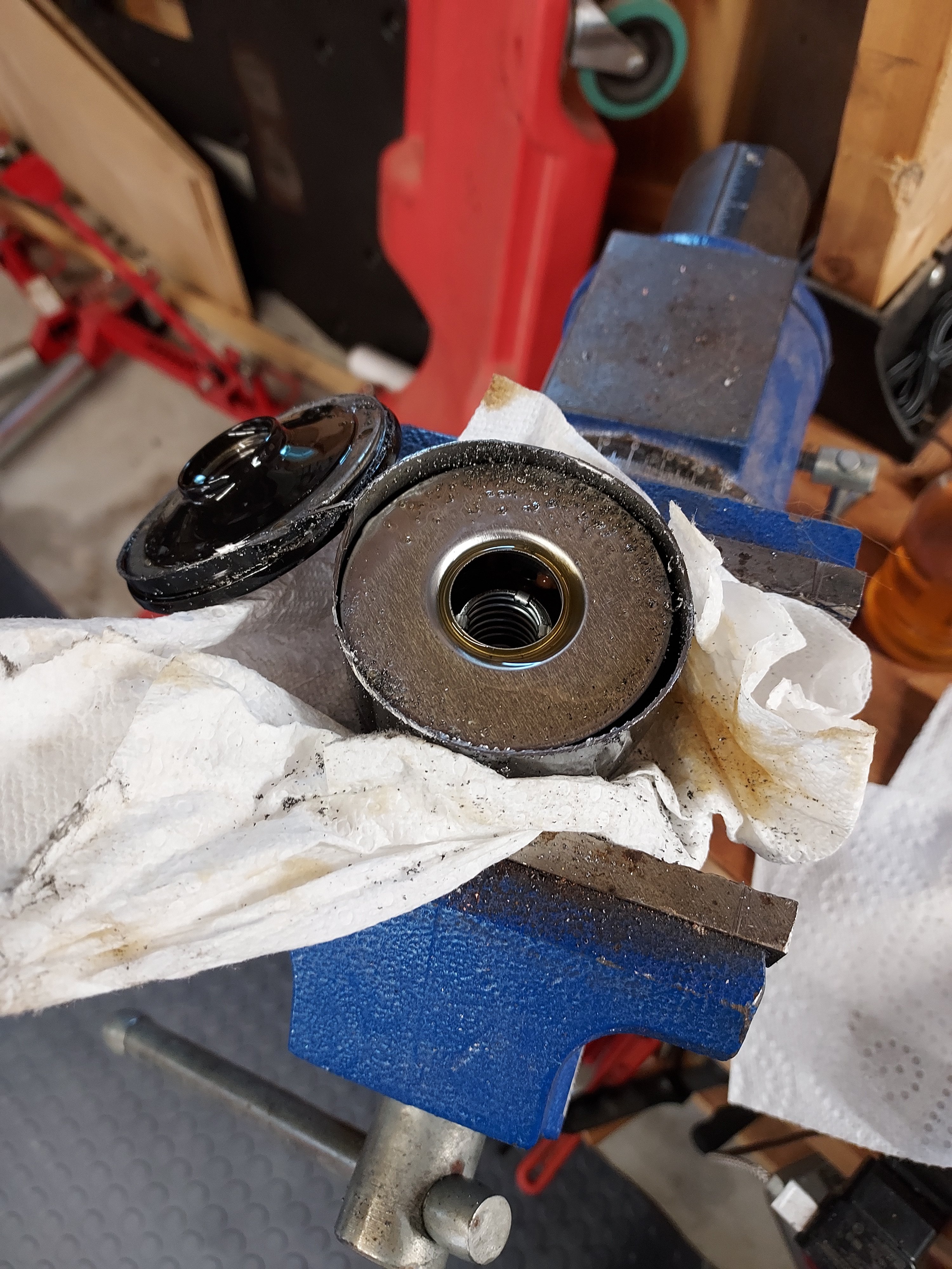
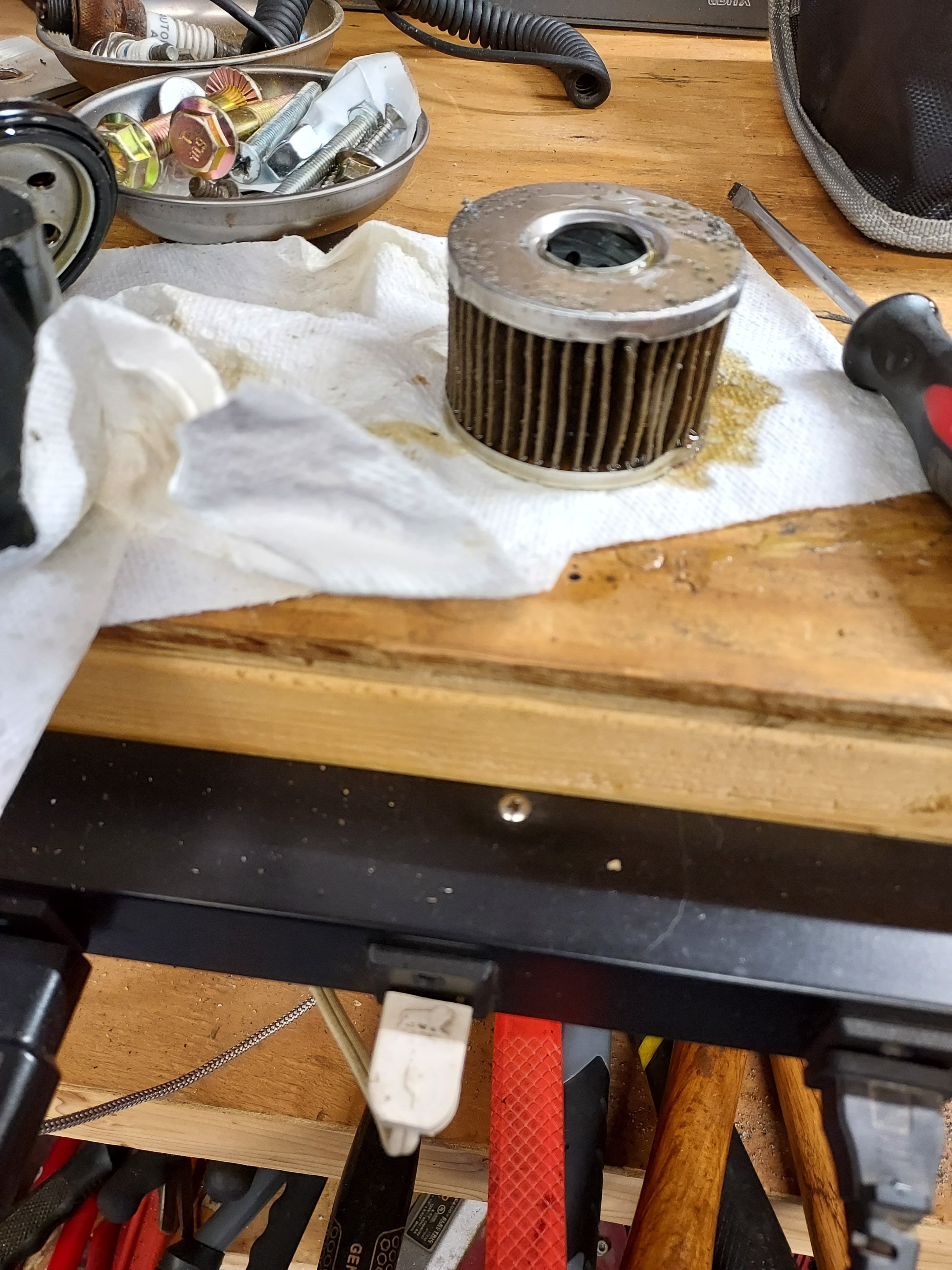
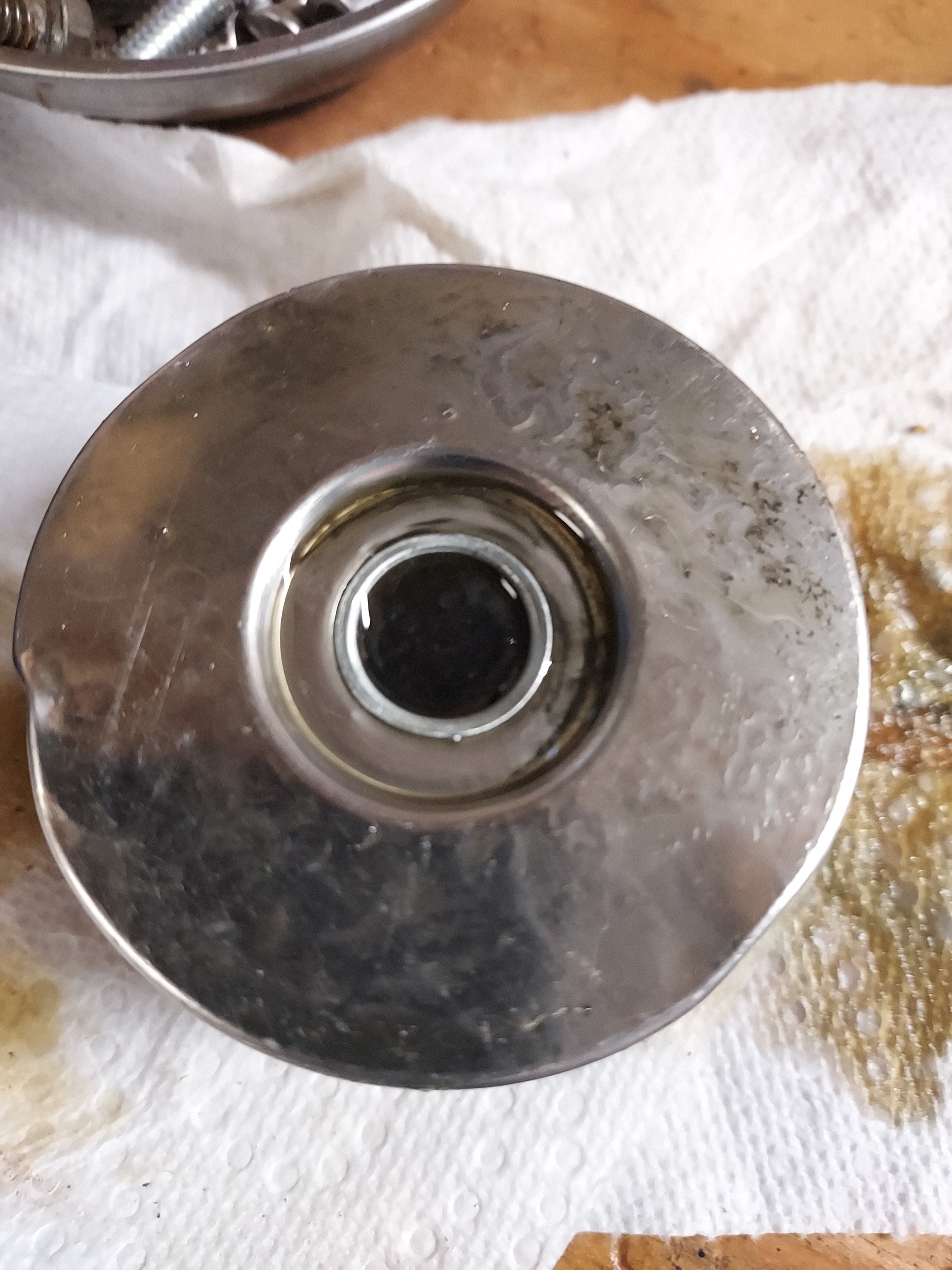
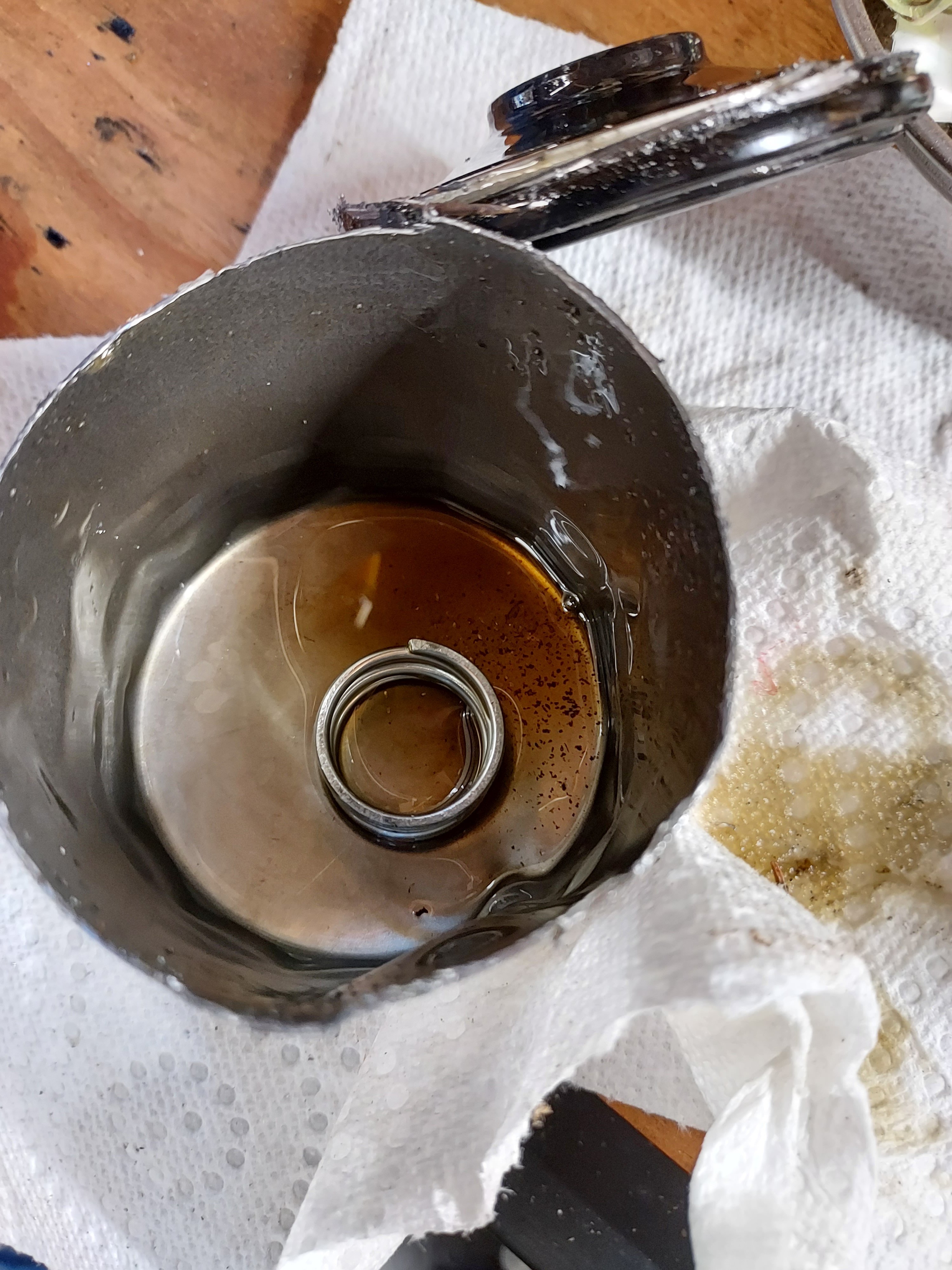
I've been looking for a cross to a filter from a known manufacturer since I bought this machine. Both from a cost standpoint, and a known quality standpoint. The factory filters are just plain black with no markings. Due to price point on these machines I would assume that the factory filter would be made as.cheap as possible I have not had any real luck finding a cross, so In doing my first oil change I decided to cut the factory filter and see what is inside. I don't have a fancy oil filter cutting set up, so I just clamped it in the vise and went to town with my portaband. Excuse the rough cuts and metal shavings. Looks like a good quality filter, plenty of pleats/surface area. Metal endcaps. Excuse the crushing, that's from the vise/strap wrench to remove it. Relief valve And a spring in the bottom of the can to keep the top silicone anti-drainback pressed in place. Overall looks like a surprisingly good quality filter for a no name. At least we can know that using the factory filters on these should be acceptable. I feel better about paying $10 for this filter at least knowing it's good quality.
-
Service manual for Hisun 750. Cannot find for download. Does it exist?
-

129 downloads
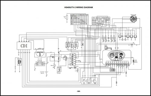
This is the latest (MY 2020+) HS400 service manual--, it is dated December 2019, I got it from Hisun and edited it to correct spelling, add bookmarks, and flag obviously bad information (they had the transmission and shift mechanism section completely fouled up, showing the 2-speed (L-H-N-R) tranny from the HS500+ models. I inserted a proper transmission shaft (input, counter and output) diagram as well. It has a great electrical diagram I posted separately a while back... -
View File 2015 Hisun Axis/Forge 110cc Service Manual This is the Service Manual for a 2015 Hisun Axis/Forge 110 ATV. It may include other years. Submitter AdamG Submitted 06/04/2021 Category Hisun
-

5 downloads
This is the Service Manual for a 2015 Hisun Axis/Forge 110 ATV. It may include other years. -
Curious if anyone has successfully added a light bar to a Coleman / Hisun 550cc UTV. I got mine at Tractor supply last November, but I understand they are the same machine as a Hisun. I've been scouring the interwebs for information regarding the wiring harness to no avail. Wondering if anyone on this forum as had success and could offer some tips. Thanks y'all
-
View File 2020 Hisun HS400 Service Manual This is the latest (MY 2020+) HS400 service manual--, it is dated December 2019, I got it from Hisun and edited it to correct spelling, add bookmarks, and flag obviously bad information (they had the transmission and shift mechanism section completely fouled up, showing the 2-speed (L-H-N-R) tranny from the HS500+ models. I inserted a proper transmission shaft (input, counter and output) diagram as well. It has a great electrical diagram I posted separately a while back... Submitter cliffyk Submitted 04/24/2021 Category Hisun
-
74 downloads
As the the filename indicates, service manual for the2017/2018 Hisun HS400 and Coleman Outfitter 400/UT400... -
View File 2017/2018 Hisun HS400 Service Manual As the the filename indicates, service manual for the2017/2018 Hisun HS400 and Coleman Outfitter 400/UT400... Submitter cliffyk Submitted 03/03/2021 Category Hisun
-
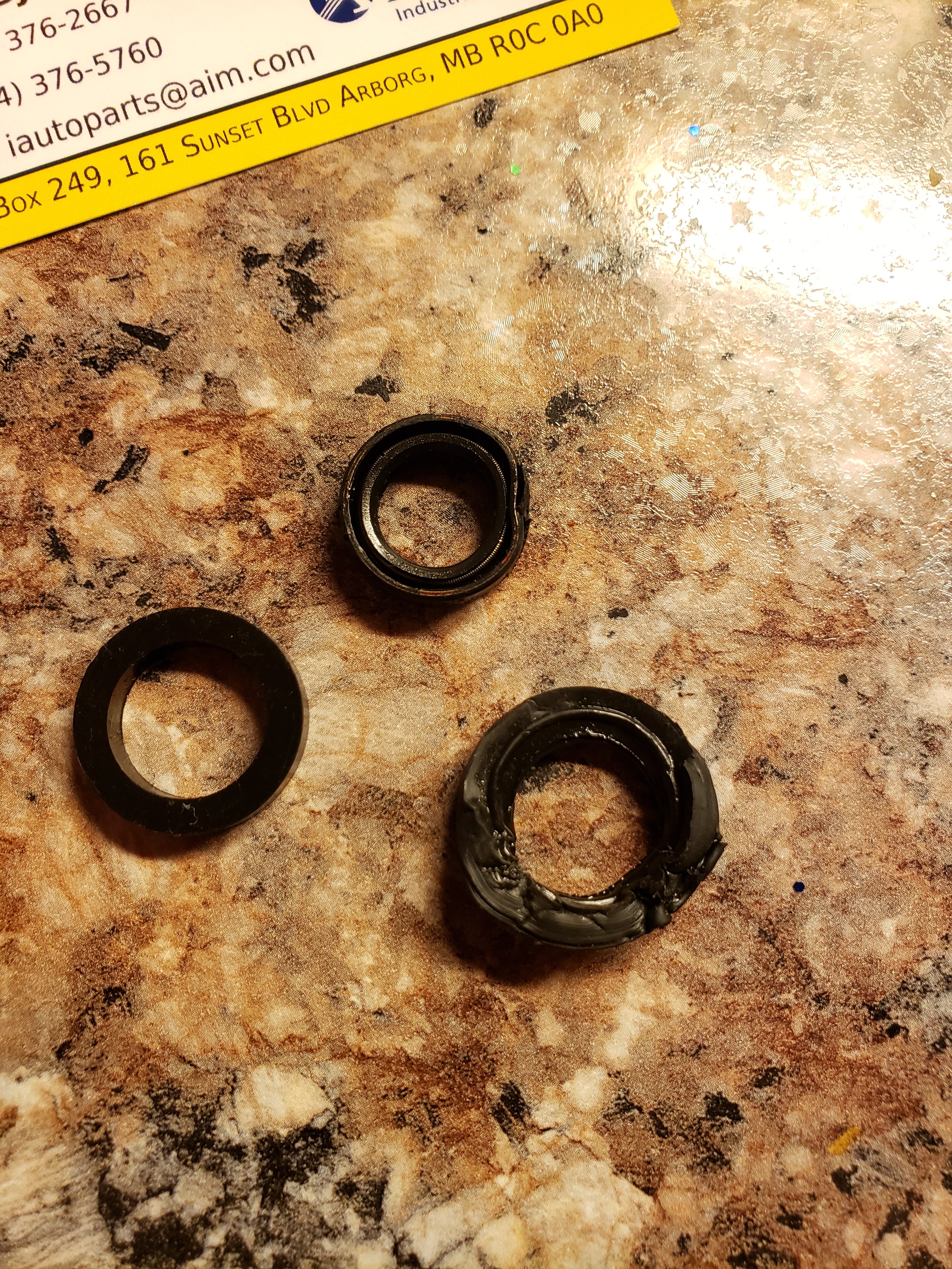
 Hi, I think I just bought a Husun 450 that is in need of TLC. It is leaking badly from the shifter shaft (located at left foot). I can not find a part number for the seal(s) 3 came off of the shaft. If anyone can help I would be extremely grateful 🙏
-
View File 2014 Hisun HS400 Service Manual 2014 Hisun HS400 Service Manual Submitter Alex Submitted 01/03/2021 Category Hisun
-

24 downloads
2014 Hisun HS400 Service Manual -
View File 2010-14 Hisun HS800 Service Manual 2010-14 Hisun HS800 Service Manual Submitter Alex Submitted 01/03/2021 Category Hisun
-

38 downloads
2010-14 Hisun HS800 Service Manual