
cliffyk
-
Posts
350 -
Joined
-
Last visited
-
Days Won
49
Content Type
Profiles
Events
Forums
Gallery
Downloads
Community Map
Posts posted by cliffyk
-
-
FWIW; I have never in 70+ years replaced a fuel filter because it needed to be replaced. I have added them to engines that did not have one--a good thing to do-; and changed them periodically as preventative maintenance, but have never had to replace one due to poor performance (most likely due to my being kind of anal retentive about PM).
Also re; adding a filter, the nipples on the filter do not have to be a precise match with the I.D. of the hose; that's why God created Ideal clamps...
Ideal clamp:

-
 1
1
-
-
Hello all,
While "surfing" at Amazon I stumbled across this Wireless Winch Remote Control for $17.
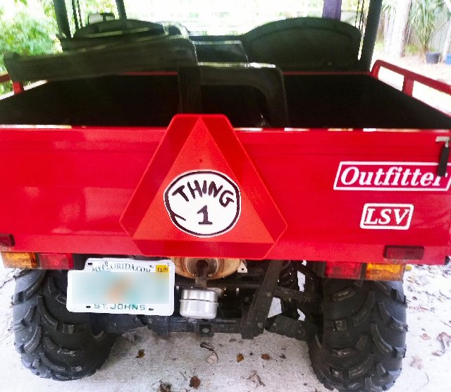
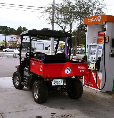
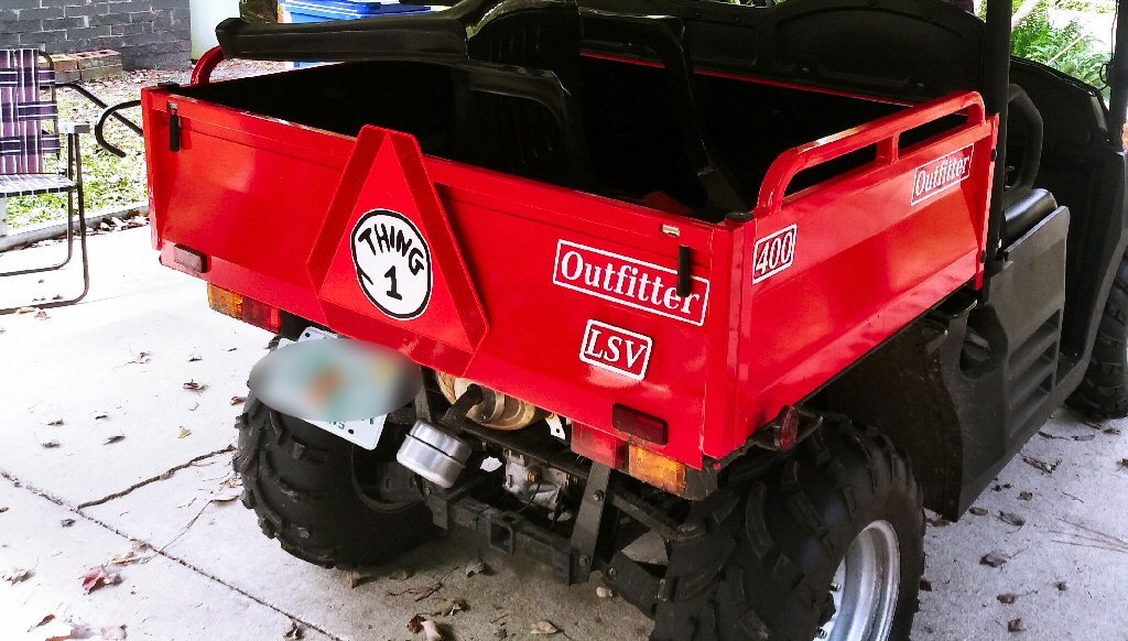
It comes with absolutely NO documentation, but fortunately I was able to garner what I needed from scouring the web and examining the wired pendant controller that came with the "Thing" (what SWMBO calls my Outfitter 400).
Once installed I found it performed just as claimed and in fact better--my testing found the remotes to have a solid 120 + ft range--though I cannot for the life of me envision a situation where I'd want to run the winch from 100 feet away? The control module is fully potted and waterproof, the remotes are well made and as sturdy as they need to be, HIGHLY recommended!
If anyone is interested I can post photos and a wiring diagram...
-
1
-
-
I had mentioned in a previous post that I had removed the front anti-roll bar from my 2020 Outfitter 400; I ran that way for a month or so without noticing any downside however recently I installed a 'suicide knob" (see below) to assist my Parkinson's disease affected arms in turning the beast--but after doing so i found that in the quicker, tighter turns the knob permitted the vehicle would nosedive a bit, dig in, and plow on hard surfaces--not scary, but quite noticeably.
So I put the bar back on. Then today I got about 1-1/2 miles down the main road on the nearby power lines, turned around and came home to take it off--with the bar on, at 25 to 30 MPH, the front-end of the beast jumped like rabbit at each bump in either wheel rut., for a nearly brutal and quite uncomfortable ride. the bar (20 mm solid steel) is far too robust for the weight of the vehicle. The front bar on my 3900 lb. Infinity M37 is 30 mm...
suicide knob--for you younger folks:
-
1
-
-
While you are there, check out NirSoft's other stuff--I have been using many of their utilities for years...
-
1
-
-
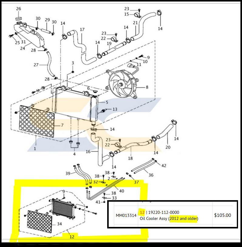
Another anomaly; In looking at parts lists for the Coleman and its cousins (the Massimo MSU400 and Bennche BH400) I ran across this reference to the engine oil cooler:
Note the "(2012 and older)" annotation re: the oil cooler-- My 2020 Coleman UT400 has the engine oil cooler...
-
The owner's manual provided on Coleman's site does not even accurately reflect the machine shown in their video on the same site. In the video the vehicle clearly has a steering column mounted ignition switch--while their manual depicts a dash-mounted switch. Also the gauge cluster shown in thw video isw like that in the machine I have--the cluster described in the online manual is entirely unlike that in my vehicle--the manual provided online by Coleman is wrong about most everything
gauges/controls from video heading Coleman's site:
gauges from on-line owner's manual:
Then there's the whole bit in the manual about using the choke to start a cold engine:
It's an EFI engine, no choke--I feel sorry for those owners that spend time looking for a choke...
-
 1
1
-
-
I acquired a Coleman UT400 just after Thanksgiving (2020) and find it to be quite different than most others seen on the web--the most visible difference is that the cylinder slants toward the rear placing the "hot spot" under the bed rather than under the seat (a significant improvement to my mind). THe curious prt of this is that neither Coleman nor Hisun seem to acknowledge this major design change. In fact the Owner's manual supplied with the vehicle appears tp haqve been written for a completely different unit--showing the ignition and light switches mounted in the dash (they are stalk mounted on the steering column on mine) and indicates that to change the spark plug requires removing the seat (the cylinder head and plug are under the bed on mine):
I wrote to Coleman and they sent me a what is supposed to be the most recent "UT400-5" manual which is still wrong about 90%+ of the vehicle. Neither the Coleman or Hisun websites are of any use as their content provides no photos and very little information about maintenance or the engine/drive train in general.
Is anyone aware of when these changes were made, or of any sites offering info re: this latest mode? Currently I'm battling shift cable adjustment to find better and more consistent reverse gear selection.
Mine also differs in that the parking brake is a single caliper and disc mounted on the rear differential pinion shaft (this seems to be a "5 brake" configuration I have found reference to.
Overall it seems well designed and manufactured--the chassis welds are as nice as you could ask for and the castings and machining are top notch.
Any information or suggestions as to where to look would be appreciated...
TIA
-
1 hour ago, Bret4207 said:
Cliffy, that set up is on a Briggs Vanguard, not the Hisun/Coleman. We just got off on a tangent. The Briggs had the same set up only they used a relay where I use a toggle. Thanks for the thoughts though!
I reread the thread and found where I went wrong. I believe the Vanguard series still uses a plain ol' magneto design ignition with magnets in the flywheel and an armature type HV coil, shorting the armature to ground is the classic stop/kill switch technology for such systems--it's been in use for well over 60 years of my personal experience--since when we built go-karts from bed rails and engines salvaged from old reel-type mowers--and I suspect yours as well..
-
On 12/20/2020 at 9:02 AM, Bret4207 said:
At this point the 2 coils are not connected to anything but a ho'made kill wire run to a toggle switch and to ground on the engine block. Pulling the shrouding to access the coils involves diassembling both sides of the drive train. I should have cut the shroud horizontally last time I had to do this!
First thing I'd do would be to get rid of that--however there's no telling what damage being shorted to ground might already have done to the ECU. Properly configured the ignitor output of the ECU never sees a direct short to ground connection--it creates one to dump the coil's charge and generate the spark, however it is never connected directly to ground on a continuous or even intermittent basis.
-
No one wants them--if their was demand makers would be making them available--as added cost options if nothing else.
-
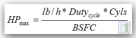
BTW: fuel injector flow is pretty much directly relaed to the maximum HP an engine can produce--per this formula:
BSFC = Brake Specific Fuel Consumption; the rate of fuel consumption divided by the HP produced. The rule of thumb value for naturally aspirated gasoline engines is 0.45 to 0.5 pound per hour per horsepower. So, our 27.77 l/h injector operating at a not actually feasible or possible 100 % duty cycle could (if possible) support:
(27.77 * 1 [100%]* 1 [cylinder]) / 0.45 [BSFC] = 61.7 HP.
But at practical 75% duty cycle --and assuming dynamic flow rates at less than the static flow rate digress along a linear curve (hint: they do not)-- we get:
(27.77 * 0.75 [75%]* 1 [cylinder]) / 0.45 [BSFC] = 46.28 HP.
Or more likely 40 to 44 HP in our real world.
Back in my supercharged Mustang and Miata days I spent a lot of time pouring over crap like this
-
"Static flow" rate is the flow in units of quantity per unit of time with the injector held open. The 280 and 292 values are the flow in cc/min (cubic centimeters per minute)--divide cc/min by 10.5 to estimate the flow in lbs/hour (pounds per hour).
Gasoline weighs 6.073 to 6.2 lbs per gallon (87 to 93 octane);
one gallon = 3785.4 cc,--therefore 1 cc = 0.00026417 gallon = 0.0016043 pounds (87 octane);
1 cc/min (87 octane) = 0.0962583 lbs/hour (0.0016403 * 60);
292 cc/min = 28.1 lbs/hour (292 *0.0962583) (87 octane)
It looks like Injector ℞ used 6.0 lbs/gallon--close enough...
At 6.0 lbs/gallon, 1 cc/min = 0.0951012 lbs/hour; * 292 = 27.7695 lbs/hour.
-
1
-
-
I have never needed to replace a fuel injector in anything--I have upgraded them to higher capacity numerous times. Cleaning them is easy, I connect a 4" or so long piece of vinyl tubing; of appropriate ID to fit snugly; to the outlet end of the injector,. Next fill the tube with cheap Super Tech carburettor cleaner from Walmart. Pressurize the tubing with compressed air to 40 to 45 psi¹ then activate the injector. Do that 2 or 3 times and it will be clean. Some do this from the inlet end, however I have found back flow flushing to be more effective.
I also have a rig using a 100 cc graduated column (actually a big syringe) that allows me to time how long it takes the injector to squirt 100 cc of fluid--I use naphtha--that provides a pretty good indication of it's flow rate.
CAUTION: Make sure you do any of this in a well ventilated area--and use an enclosed switch to trigger the injector. Flammable aerosols and nearby sparks can make bad things happen!
---------------------------------------------------------------
¹ - Most fuel injectors are rated at an operating pressure of 3 bar (43.5 psi).
-
1
-
-
I recently acquired a new 2020 Coleman Outfitter 400 and overall am quite pleased with it. I had the "too be expected" loose bolts (first thing I checked), all related to the final assembly conducted by the pimple-faced kid "mechanic" at Tractor Supply.--the bolts in the upper driver's side roll bar joint were just hand tight, as were those of the upper seat belt anchors--but other than that it had been pretty well assembled.
The included owner's manual is not current; it speaks of using the choke to cold-start the motor (it's EFI, no choke), and shows the ignition and lighting switches as dash-mounted when in fact they are on the steering column. It also direct you to remove the seat to change the spark plug--except that on this revision the cylinder tilts rearward and the cylinder head in found beneath the dump bed. Other maintenance tasks are similarly ill-described and it is generally useless.
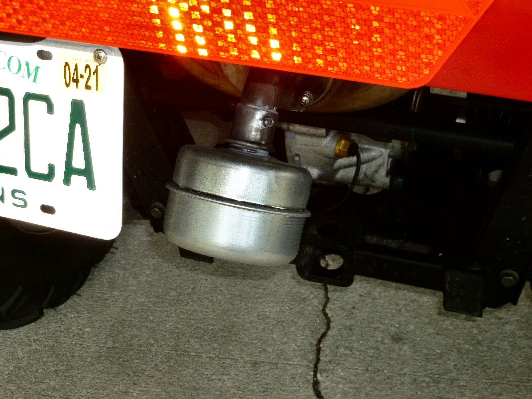
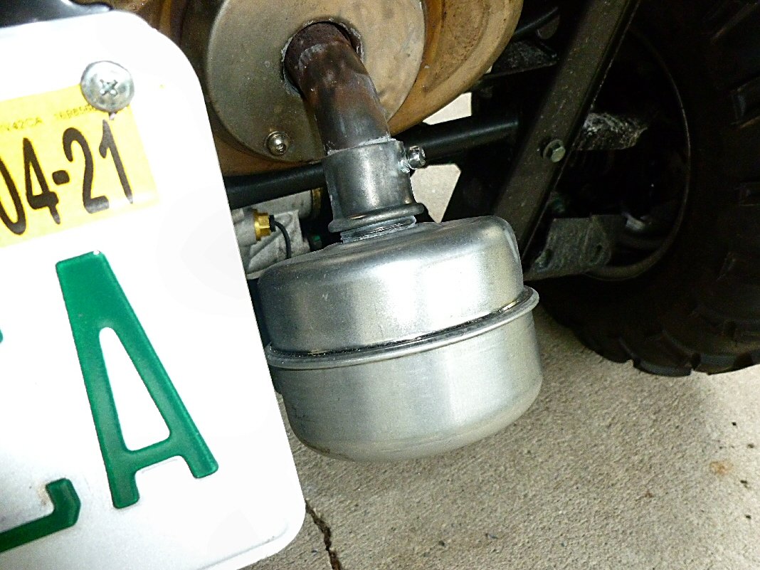
I did find the exhaust note to be a bit strident and devised the following to tone it down a bit. I used one of those inexpensive 1" NPT female inlet B&S "muffin" mufflers that have been around for decades, and a steel 1" EMT to steel box adapters that have been available for a like time:
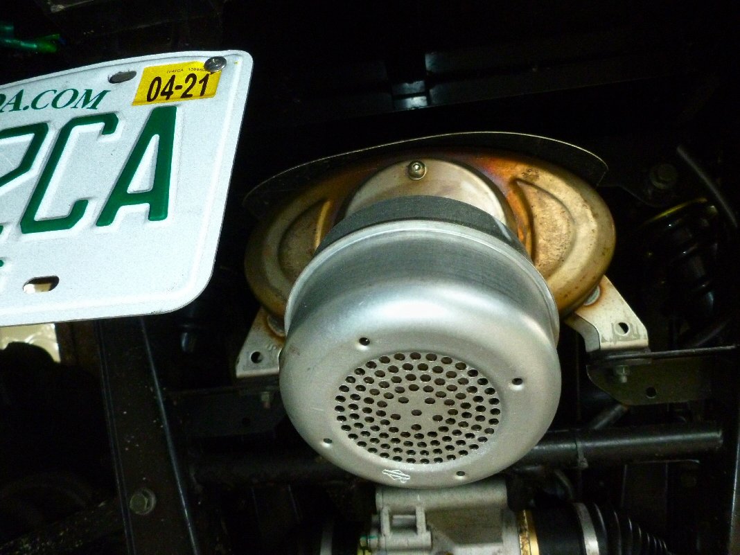
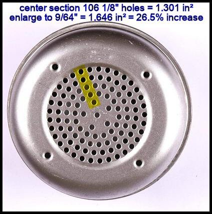
1" EMT has an outside diameter of 29.5 mm, the tailpipe extension on the beast is 28 mm O.D.--so I use a partially overlapped cylindrical shim spacer of 28 ga. (0.47 mm) galvanized sheet metal to fit the EMT adapter to the tailpipe . Bedded well in muffler putty the single set screw on the adapter mounted it up quite firmly.On my first ride I found the motor to feel and sound a bit constipated--so i drilled out the 106 1/8" holes in the faced of the muffin to 9/64". This is a 26.5% increase in area [(9/64)^2 / (1/8)^2 = 1.2656]
That made the difference needed to restore proper flow without making it too loud again:It
is arguably not a pretty as some of the $100+ aftermarket alternative, but at $15 for the muffler and adapter it better fits my budget.Make sure you get the genuine B&S part (# 392989) as the 3rd party clones lack an inner baffle that makes them inherently louder than the B&S piece.
FWIW--I also removed the front anti-roll bar--and have found little to no adverse effect on handling (and arguably some positive effect)--it also got rid of an annoying rattle from the low-quality driver's side roll bar tie-rod end. Put in an iridium spark plug too...
[update]
For anyone who cares. I have re-drilled the 106 outlet holes to 5/32" which seems to be a sweet point.
I had the beast running 45 mph (indicated, 40 by GPS) t'other day and it felt a bit "held back" so when I got home I hogged out the holes to 5/32"--another 23.4% area on top of the 9/32' holes (56% more than the original 1/8" holes). Went out today and got it going 53 mph (indicated, 47 per the GPS). Coleman and Hisun claim 38 mph top-end for the HS400 but I knew it had more than that.
So, I Think the 5/32" holes are about optimal.
I need to take the B&S thingy off and see what it can do, however it (the B&S thing) is so nicely mounted and sealed now that I don't want to mess with it...
[/update]
-
 2
2
-


HF Synthetic Winch Rope--[updated]
in Coleman UTV SxS Forum
Posted
Hello all,
In looking for a synthetic line for my Outfitter 400's 3500 lb. Runva winch I ran across this offering from Harbor Freight; $30.99 with 20% off coupon + tax = $26.40--not too bad (please spare me the "Cheap Chinese junk" yowls, where do you think 99.44% of the components of, and stuff we buy, for our toys comes from?).
It is made of UHMW polyester with a claimed (and fully believable) tensile strength of 4700 lbs. and a working load of 3000 lbs.--which is in keeping with the specs published by most manufacturers of UHMW rope and therefore much more believable than the 6000 and absurd 8200 lb. claims made by other vendors. It comes with a G70 snap-hook (sized for 1/4" chain), and an anodized aluminum Hawes type fairlead. The package I bought did not contain the red strap shown in HF's ad, which based on reviews is a common failing of the kit. Also, there is no snubber provided, I got a nice one of silicone rubber with stainless fasteners from Amazon for $7.
The winch and business ends of the rope are sleeved with black urethane coated nylon (were i to guess) protective sleeves-for 8+ ft at the winch end and 5 ft. or so at he hook end. The winch end has a couple inches of heat shrink tubing to prevent unravelling and assist in fastening it to the typical bore-through/set screw winch drum. The 12-strand braided rope appears to be of a high quality UHMW polyester, as claimed, the fairlead is cleanly cast and appears to have been glass bead or shot blasted after casting a it has a smooth fine pebble grain finish. The mounting holes are at the standard 124 mm (4-7/8") center-to-center distance as is common on ATV and UTV winches.
All 50' installed easily on my winch, the 8 ft or so of protective sleeve providing a nice supporting first wrap. The sleeve at the business end completely covers the last layer of rope, providing a nice shield to protect the synthetic rope from prolonged UV exposure. Likewise, the fairlead bolted right up with no problem.
on the drum:

the Hawes fairlead and snubber:

long shot:

It is important to keep in mind when using synthetic winch rope that, while it is very strong, it is also very low stretch, typically just 3.5% at break--in practice this can result in dynamic shock loading exceeding it's tensile strength. This is also true of steel wire rope, but the metallic rope can better handle dynamic loading.
I also would not recommend synthetic rope for use in that torture track that is common to winch hoisted low-cost ATV/UTV snowplows. The mechanical dis-advantage which most plow designs operate and apply to the winch hoist is staggering. In such plows am less surprised that the rope (synthetic or wire) breaks than that it survives more than one use.
I like it...
[update 02/04/2021]
After some experimentation using a digital scale, a 55 lb. anvil and both the roller and Hawes fairleads I have re-installed the roller fairlead. I found that at extreme fleet angles (45° to 90°--angles you should try to avoid) the Hawes fairlead increased required cable load by 10% to 25% vs. the roller fairlead.
One caution however; make certain there is sufficient overlap of the roller faces and the ends of their companion rollers--both ways. On my roller fairlead the rollers overlap the ends of their 90° opposed companion by 1/2 their diameter as illustrated below:
roller orientation, my fairlead--top view:
roller orientation, my fairlead--side view:
I have seen roller guides in which this was not the case which allows the much more flexible synthetic line to "fall off" the active roller and jam between the end of its companion roller and the fairlead frame--which would of course be bad.
While I had it apart I also stitched and whipped the protective sleeve to the rope at both the lead end of the trailing length into the winch, and the trailing end aft of the hook.
winch end:

hook end:

anchor point on the drum:

sleeved rope in fairlead:

[/update]