
Leaderboard


Popular Content
Showing content with the highest reputation since 06/01/2026 in all areas
-
Unplugging the connector doesn't cost anything and does not suggest one should not wear the seat belt. However, freedom of choice is ours in this country and as long as we accept the consequences of our choice it should not be judged by big brother.2 points
-
I had been driving for about 15 minutes, everything fine. All of a sudden the engine was surging, losing power, would run with 1/2 throttle or greater and was backfiring badly. Luckily I was close to home and got it back. The tipoff to me was that I thought I was hearing intake noise. Sure enough, the rubber boot which connects the air cleaner and intake piping to the throttle body came loose. Obviously the computer was confused. It turned out to be an easy fix, but this is now added to my inspection list. Just thought this might help someone else.1 point
-
Tried to reply to this topic previously, not sure why it didn't go through. I think your model is fuel injected, you might try a new fuel injector. I've read where they can be sensitive to the spray pattern thus causing start issues.1 point
-
Update on resonator mods: After about 6 months I developed an exhaust leak. I don’t know if it is at all related to the mods, but I had to replace the transition pipe between the muffler and exhaust manifold (braided stainless flex pipe), along with the gaskets on each side. I think it was typical corrosion failure, but one thing I noticed during replacement was that one of the exhaust manifold retaining nuts had come loose. That may be related to the additional mass and resonance on the muffler, particularly if the nuts weren’t fully torqued originally. Anyway, if you add any silencer piping past the muffler I recommend you check the manifold nuts for tightness.1 point
-
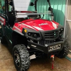
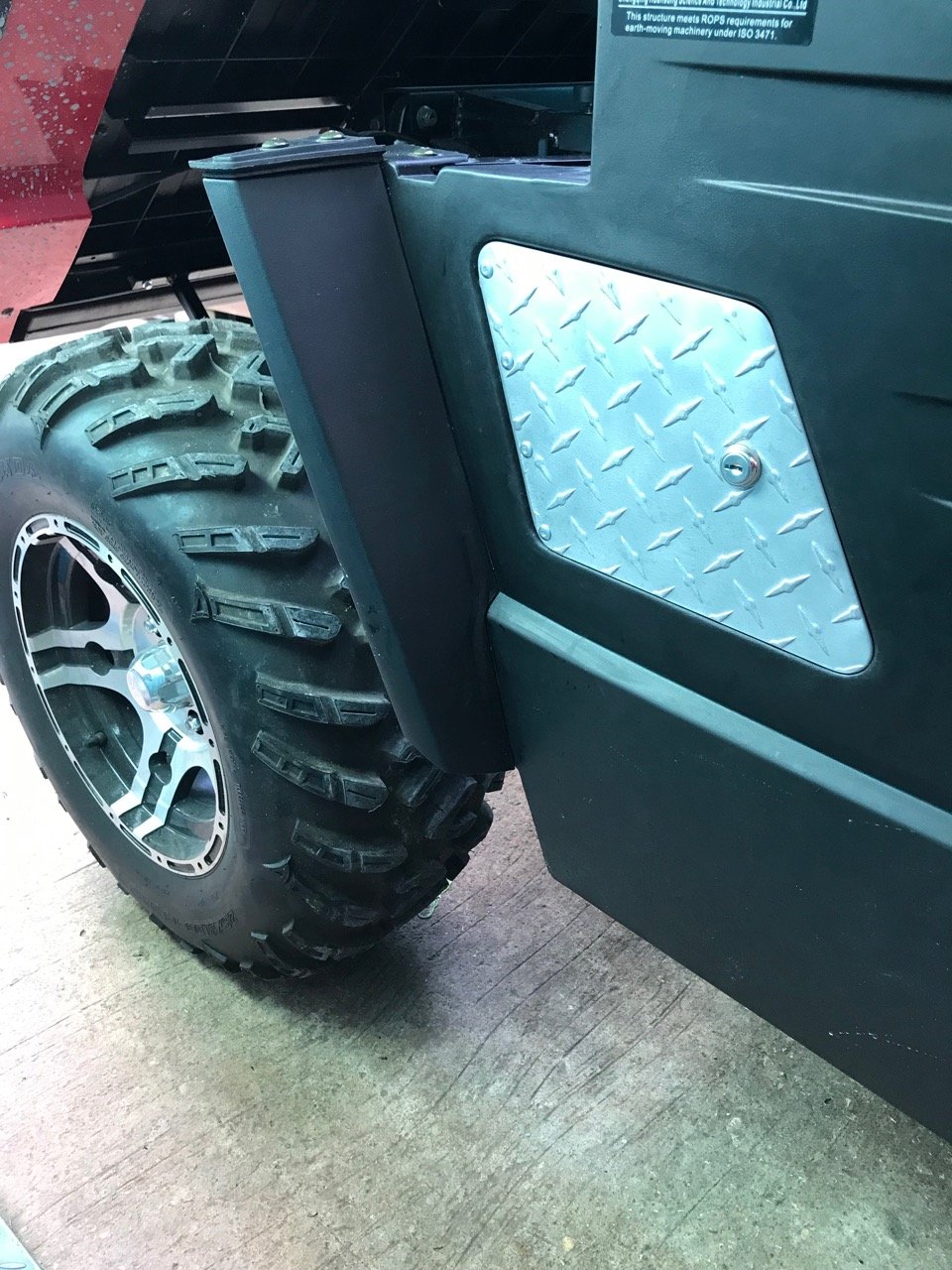
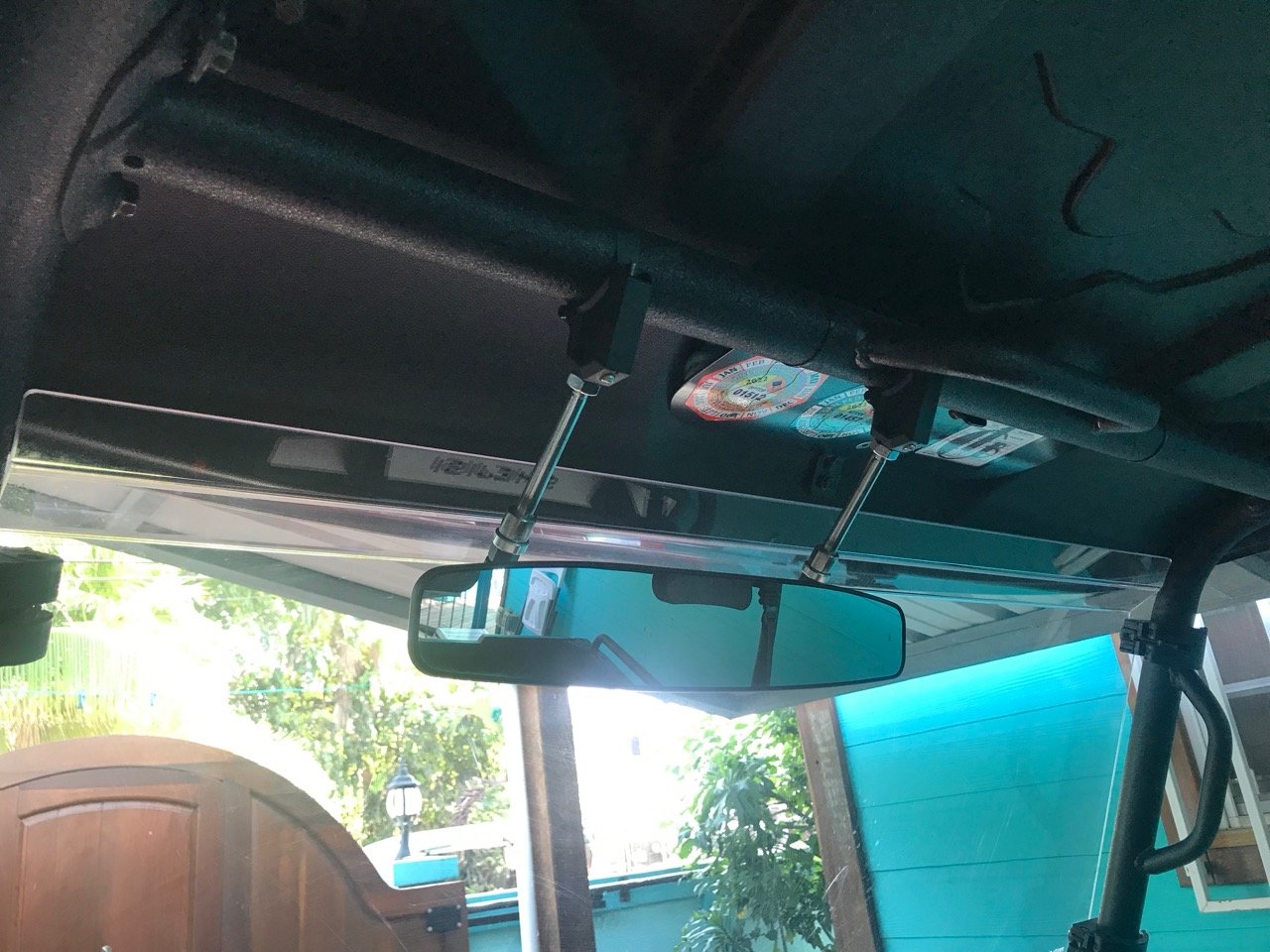
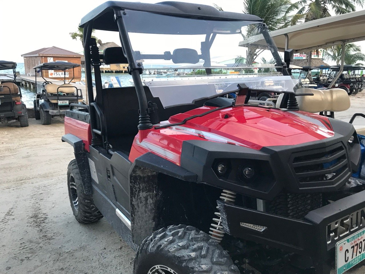
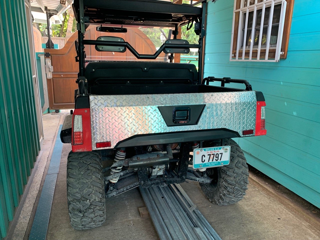
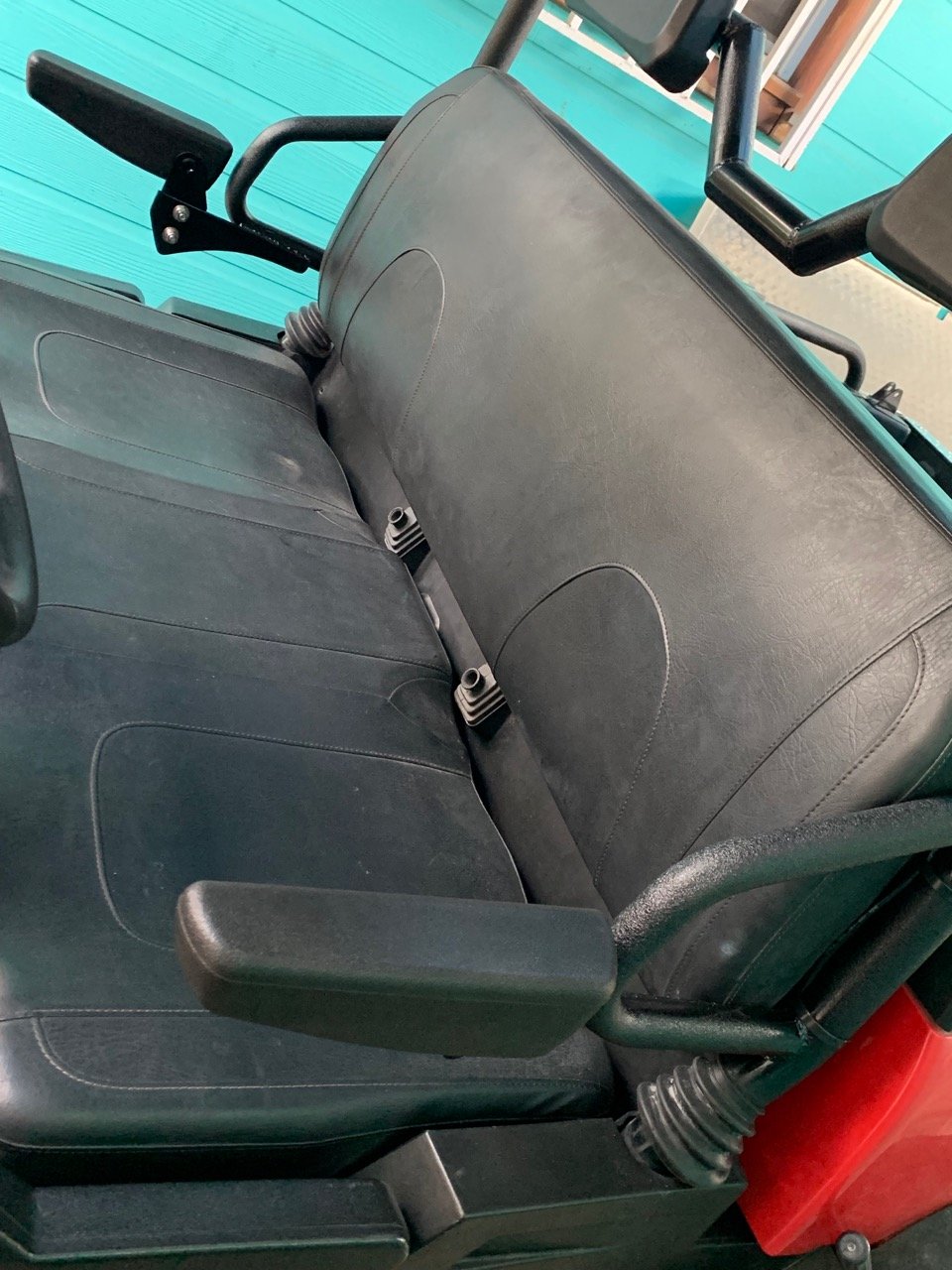
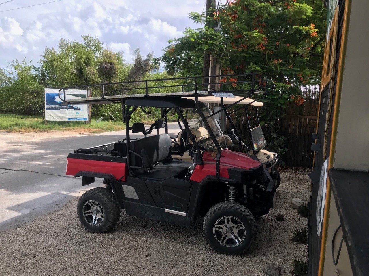
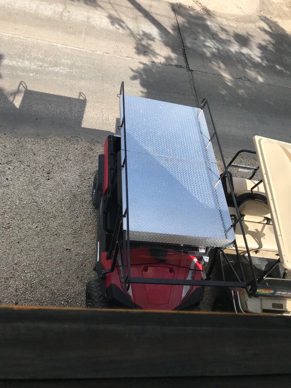
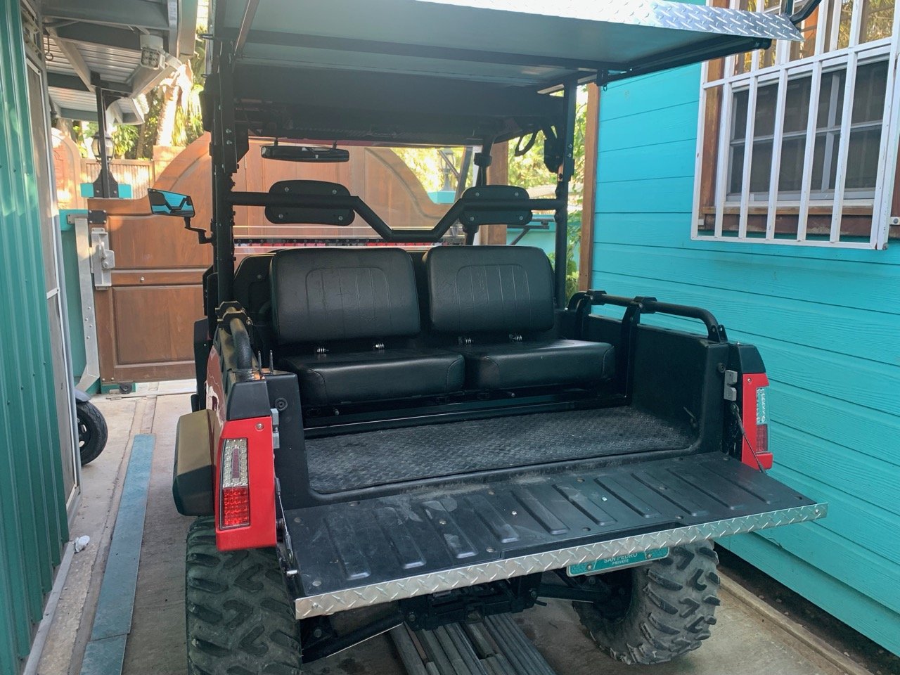
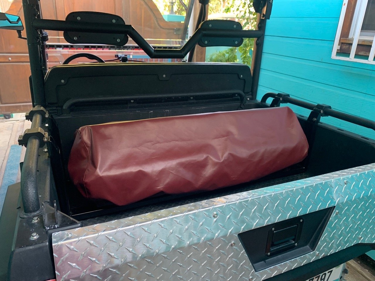
Haven't posted in a while since solving the excessive cabin noise issue, so I thought I would share a few upgrades to my Sector... Realize that this is driven daily on the street, so some of the mods are to make it more streetworthy. Locking gas door. Rear view mirror. Modified windshield for better airflow in cabin. Lowered and modified headrest bar for improved rear view. Tailgate protector. Folding armrests. Overhead utility rack. Keeps the interior cooler and dryer, too! Folding rear seats. Dust cover and seat protector. If anyone wants links to the rear view mirror, seats, or arrests, let me know and I will post. But know that everything requires some level of fabrication. The utility rack was all custom built. Cheers!
 1 point
 -
I have a screen. It helps but does not cure it. Running with front vents open also helps.1 point
-
1st buy from a reputable dealer w their own service dept. I own a dealership in DFW and when someone buys from us we take care of legitimate warranty work regardless of hisun pre approval and we pre delivery inspection before we accept from hisun and then our mechanic does a full inspection before it is ever offered for sale, BUT if you bought box store to save a couple bucks ( you don't really as our units have far more options standard but some people only think $ 500 cheaper) they are never inspected just dropped off a truck to sit till you buy it. Box stores offer no service either - NONE! we are an authorized service center but we don't wait for hisun to approve your work if you didnt buy from us, we get it done BUT you pay for the work upfront and get reimbursed what we get when we get it and no more. So buy from a GOOD DEALER and you will get taken care of if needed without a wait for warranty approval. Plus we have numerous sources for new parts besides hisun older parts if necessary off salvage units we buy. As for massimo/ hisun as a person replied in dec 2025, hisun hasn't built Massimo branded units in many years as I inderstand because of massimo failure to handle their own customer issues on their rebranded product. Matches what you said about massimo issue you had, but massimo is the distributor and accepts that responsibility. Bad Boy UTV current does same w Hisun but they are Bad Boys units and BB responsibility. Hisun takes care of hisun branded product. Additional hisun use to be imported by a distributor in US much like massimo but Hisun factory took it back from distributor due to service and bad reputation problems with that distributor. Now Hisun is hisun owned and making big push to build US market and take care of customers. I call the head of Hisun US and he always answers or calls back promptly and is very motivated to help if we have an issue. If we cant find or fix something they will send head factory service person out to our shop to help. As for bad reviews, most people only do a review if unhappy so they tend to be higher. Also many never even owned one and post bad comments because it is Chinese, but truth is many parts and components for all brands are made or built in China. Finally, go to Facebook group for Hisun. Tons of happy long term satisfied owners. The 400 model has been around for ever, is almost just like a mule and people have owned and run them for years and love them and it's the base cheapest model. Finally all brands gave problems on some units. A friend had a can fully enclosed H and A. O paid over 40k and problems from day 1 and finally forced can to buy it back! Years ago I had Polaris unit. Would just die a refuse to restart for hours or days. Polaris never was able to fix it. Someone stole it from my farm and didn't even realize it was broke down again sitting there Ha! Long but hope all this helps. You can find us on hisun dealer list if anyone wants to reach out for anything. Glad to try and help out if we can.1 point
-
So here’s the setup I used to replace the Silent Rider silencer. Materials 2” 16 ga mandrel bent 90 deg elbows (2 pieces) [90 deg elbow] 2” 16 ga mandrel bent 90 deg elbow with tail piece [90 deg + straight] 2” resonator [resonator] Rubber exhaust hanger (note- only used one) [hanger] 2” butt joint band clamp (2 pieces) (note- the exact brand I bought is no longer on Amazon but here’s an identical one) [butt clamp] 4” diameter band clamp (2 pieces, local hardware store) To make the exit pipe from the original muffler, I used the original spark arrestor flange cut from the arrestor and opened the ID to fit the 2” elbow OD. Then I welded the first elbow into the stock flange and welded the second elbow to the first at 90 degrees. The orginal trim ring can slide back over the pipe into place for aesthetics. This forms the new exit pipe to the resonator. In addition, I used some 1” x 1/4” flat stock and a piece of 1/2” rod (cut from a stainless bolt) to fab up the upper hanger that bolts to the Hisun frame, and a piece of 1/8” plate formed to match the radius of the resonator that I welded to a short tab and another 1/2” bolt shank rod. The 4" band clamps attach the resonator to the plate, and the rubber exhaust hanger provides support and vibration isolation. So originally I had intended to have the tail pipe extend straight down, but the elbows I chose wound up a bit longer than anticipated and conflicted with the rear wheel. I shortened the elbow legs on either side of the resonator as much as practicable while maintaining what I estimated to be minimum safe clamping area of about 1” to 1-1/4” (which also required “notching” the band clamps on the inside bends, see photos). I was able to get the tail pipe piece off of the tire, but it’s still pretty close and cannot aim straight toward the ground. Doesn’t look as clean, but I deem it acceptable and it does not heat the tire. I will turn down the last few inches at a later date, which should also reduce sound a bit more. So how does it perform I'm sure you are wondering... ***OUTSTANDING IMPROVEMENT!*** Much quieter, particularly outside the vehicle. Definitely quieter than the Silent Rider and lower cost (at least from my perspective since I could fab up the bits). Moreover, the stainless should last the life of this vehicle. Not a simple install for the average owner, but a muffler shop or local welder could do it for you. If I had to do this again I might source some tighter elbows or I would just shorten all the legs and weld up everything including the resonator in order to get the tailpipe straight down. But I didn’t want to weld in a resonator in general just to make it more serviceable, and also definitely not until I had assessed the performance of the mods and the selected resonator. You might look at the Evil Energy ones...more expensive but it looks like all stainless. Also, the exhaust clamps I ordered do not have stainless bolts. And finally there are more heavy duty band clamps available for the resonator that I may switch to in the future. Sorry I forgot to take a picture of the resonator hanger before installing, but you should be able to see it clearly in the installed pics. Post any questions and I’ll reply as best I can.
1 point


This leaderboard is set to New York/GMT-04:00
