


aefron88
-
Posts
295 -
Joined
-
Last visited
-
Days Won
46
Content Type
Profiles
Events
Forums
Gallery
Downloads
Community Map
Posts posted by aefron88
-
-
I would rather have the winch. Pulling anything with a come always sketchy, and you're right there if something breaks. There are so many cheap winch options on the market today, that are more than adequate for occasional use.
Either way I would go with webbing straps over chains. You need at least a strap to keep from damaging the tree.
Rigging SWL should match or exceed the winch/come along rating. So a 4000 lb come along should have 4000 swl chain/strap. That would be something like 5/16" or larger in chain. All shackles, hooks, etc should have a similar or greater SWL.
-
 1
1
-
-
You mean between high low and reverse?
How high is the idle speed? It should be ~1400. If it's too high it may have issues.
What are you using for engine oil? Is the level high enough? Is it MA approved for the wet clutch? If not the clutch may be engaging partally at idle causing it to be dissicult to shift.
-
They're pretty much all on/around the throttle body area. IAT is intake air temp it's a shared sensor with the MAPlb the suction side the throttle body.
You can use a small amount of dielectric grease to help seal the connectors, don't need any on the physical connections themselves.
Like I mentioned the errors seem to be all over the place which leads me to suspect a weak ground or other shared electrical connection, rather than a specific sensor.
I'm hardly a hisun expert, bit I have a good logical troubeshooting process (rather than throwing parts) and am happy to help where I can. Let me know how it goes and we can try to troubleshoot further.
-
1
-
-
Hey Rick,
It's strange it would throw so many random codes. I know it will throw the first two if you leave the key in the on position with the engine not running for a few minutes, not sure about the rest. Was it still running (seemingly) normally? I wonder if they're old codes.
I would probably start at battery cables, and then on the cables going into the ECU and work my way thru the EFI harness (especially all the sensors) looking for anything loose, corroded, or bent.
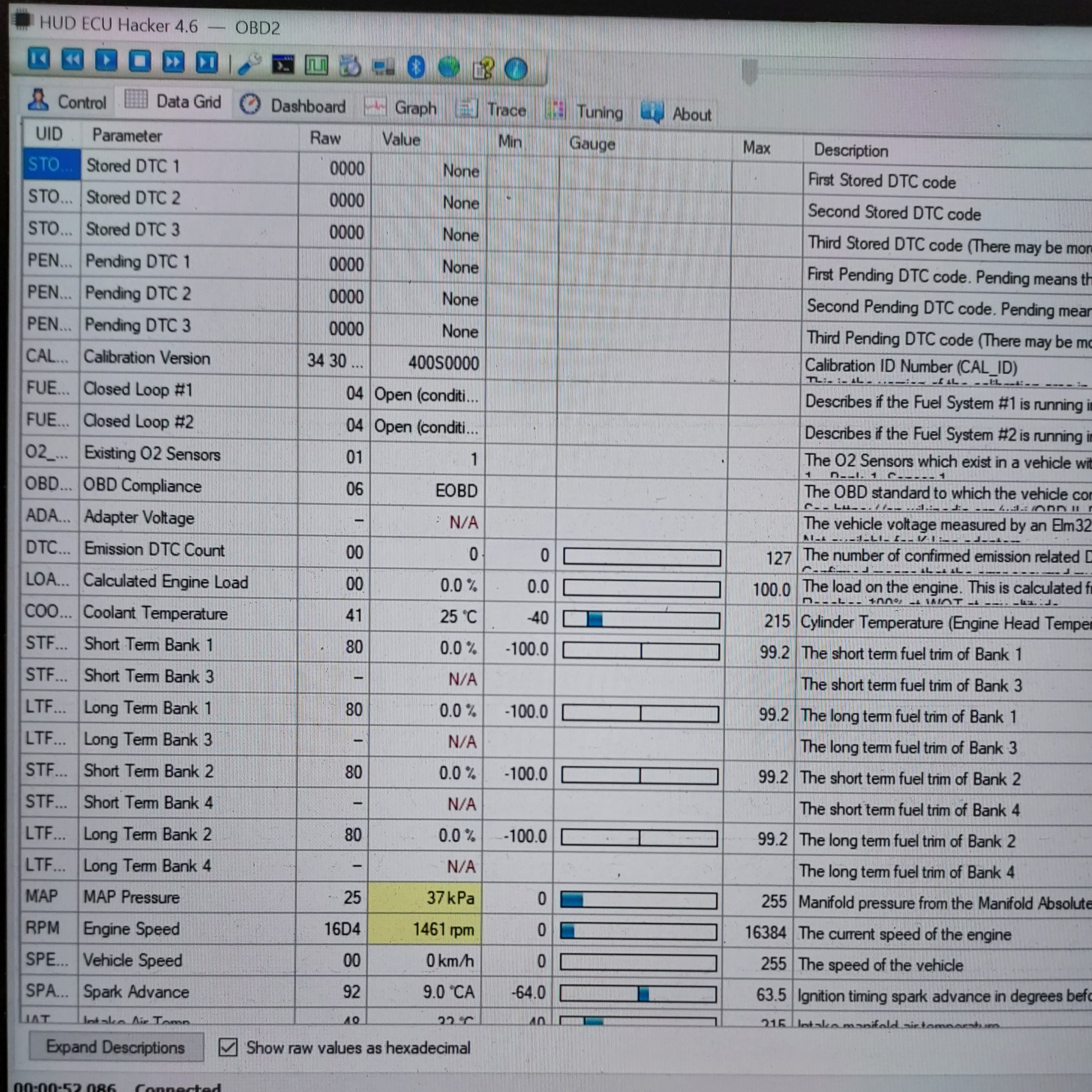
I have a post in the coleman forum that explains how to use HUD ECU hacker to see what the ECU sees that may be helpful in tracking down a random issue like this. It will also allow you to see pending codes, clear codes, etc.
-
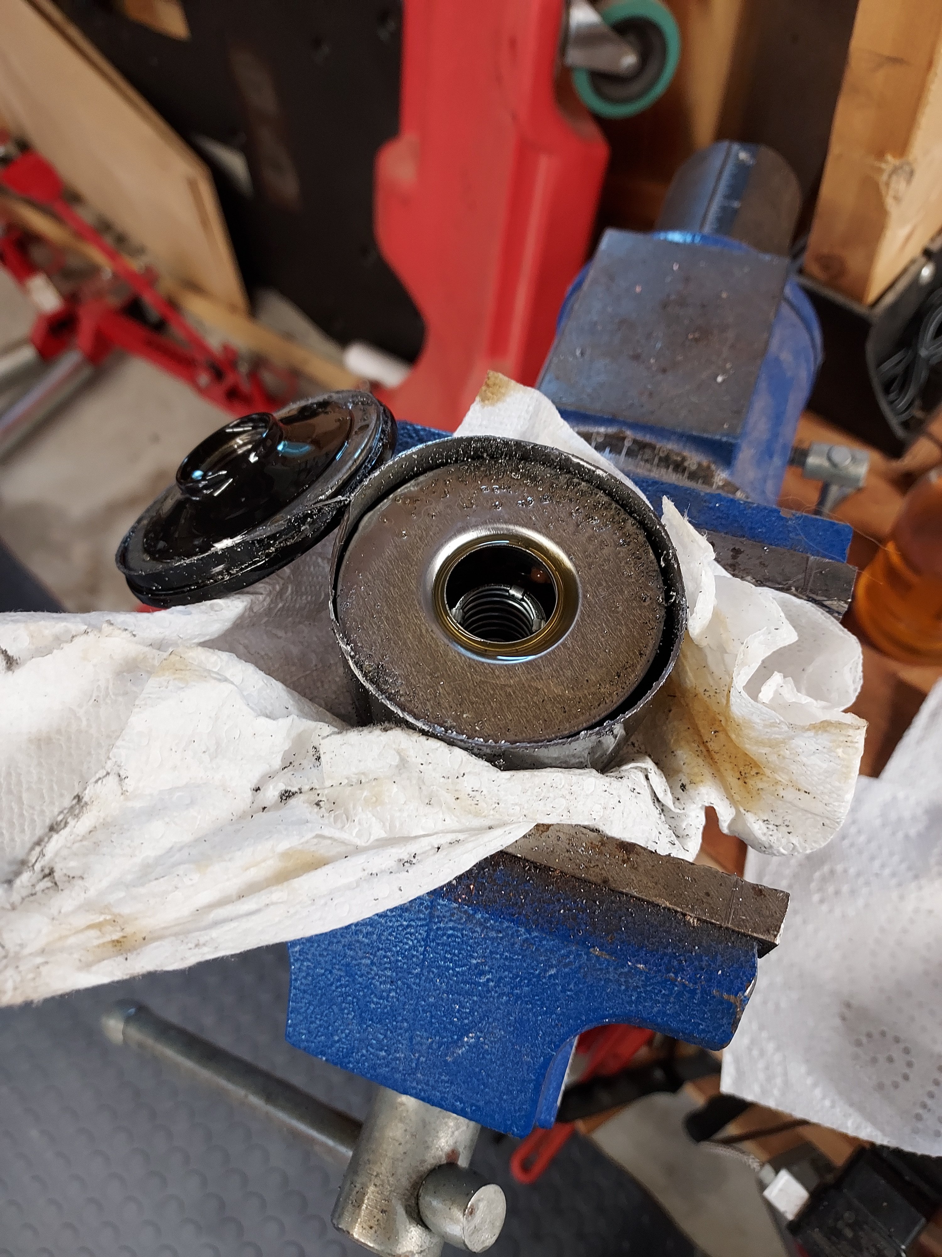
I've been looking for a cross to a filter from a known manufacturer since I bought this machine. Both from a cost standpoint, and a known quality standpoint. The factory filters are just plain black with no markings. Due to price point on these machines I would assume that the factory filter would be made as.cheap as possible
I have not had any real luck finding a cross, so In doing my first oil change I decided to cut the factory filter and see what is inside.

I don't have a fancy oil filter cutting set up, so I just clamped it in the vise and went to town with my portaband. Excuse the rough cuts and metal shavings.
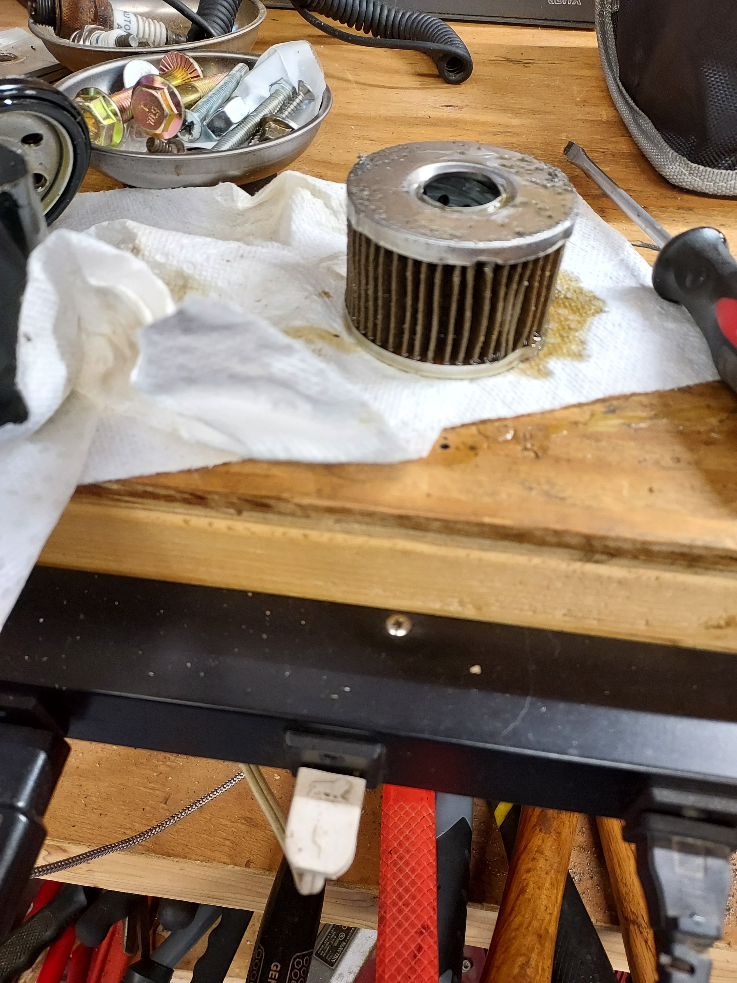
Looks like a good quality filter, plenty of pleats/surface area. Metal endcaps. Excuse the crushing, that's from the vise/strap wrench to remove it.
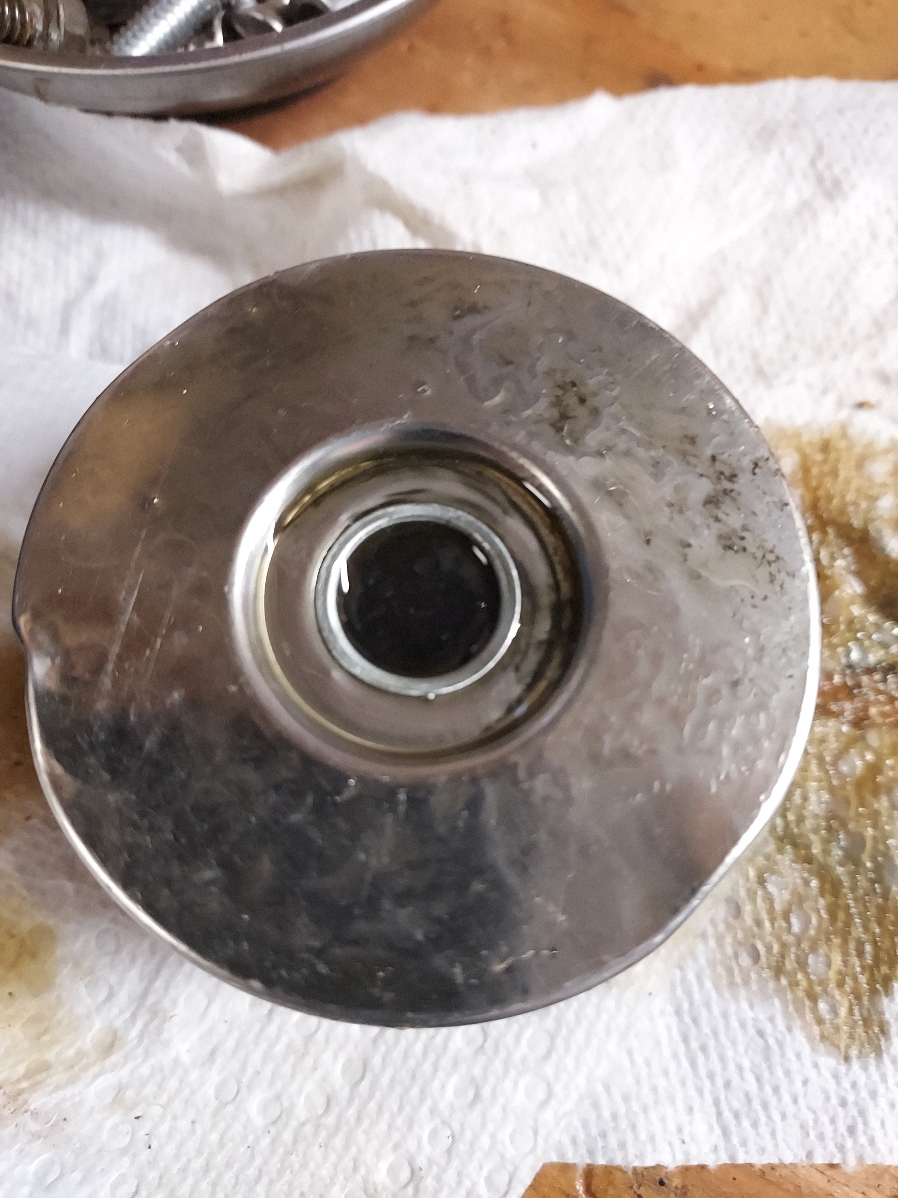
Relief valve
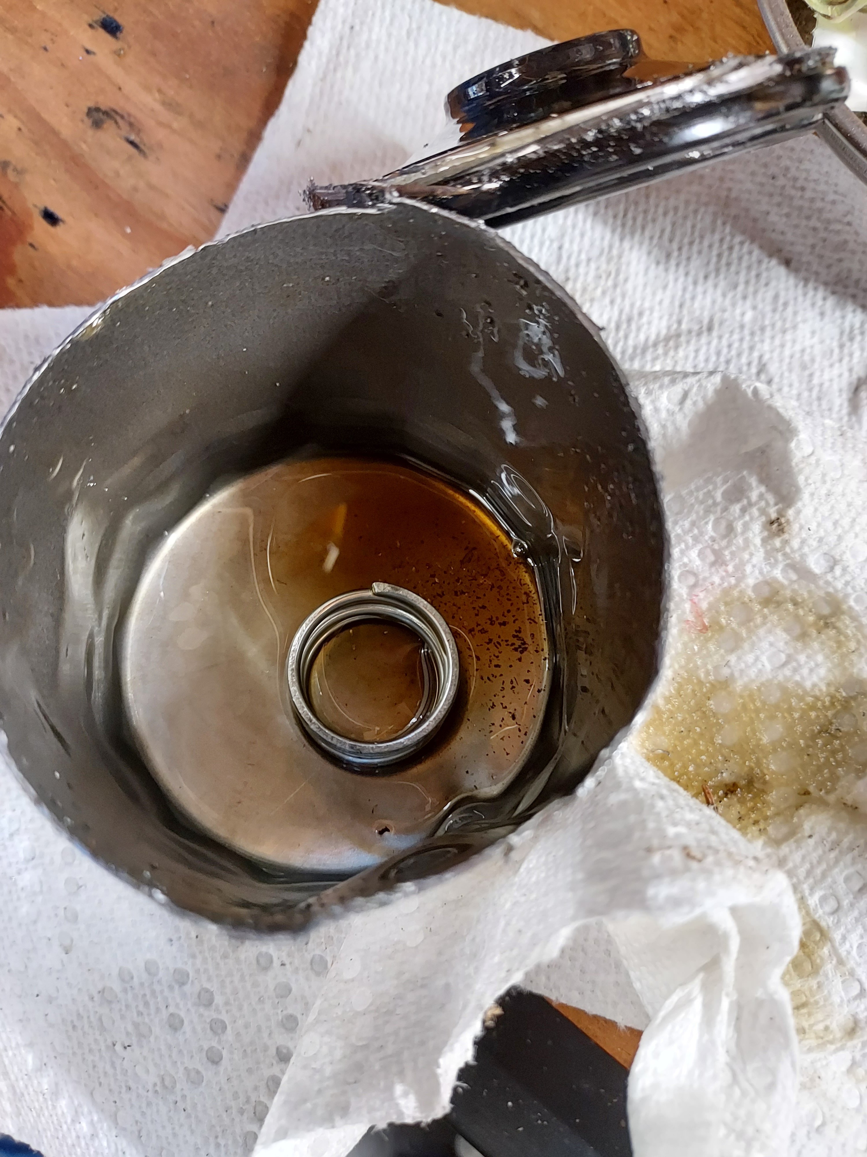
And a spring in the bottom of the can to keep the top silicone anti-drainback pressed in place.
Overall looks like a surprisingly good quality filter for a no name. At least we can know that using the factory filters on these should be acceptable. I feel better about paying $10 for this filter at least knowing it's good quality.
-
1
-
 1
1
-
-
If you're motivated it's doable., but you will likely spend a lot of time frustrated and may give up.
If you want to learn to turn a wrench you are better off starting simple with things that are easier to do, to build skills, knowledge, and confidence.
Sometimes these things seen pretty simple but can be a lot of work. Troubleshooting a motor that may have multiple issues is likely to be tough for someone with no experience, and the documentation on some of these machines is lacking to say the least.
-
1
-
-
I would start with the wiring diagram and trace the power from the batt to the fuel pump, see why the fuel pump is not getting power for starters.
-
Awesome! Better post some action shots for us once she's all back in one piece!
-
Goodluck and let me know if you run into any issues.
My cables took the slow boat from China, so hopefully yours go a little faster.
-
https://alpha-sports.com/coleman_parts.htm?q=coleman_parts
Punch in the parts numbers (the ones that end in 000) It shows the cover as $82.15.
The cover is vented to it will let dust thru. It is mainly to keep mud/water from splashing on it, and stuff from getting stuck in it. These things are adapted from ATV's and the engine/driveline setups are the same. On an atv your foot/pants would risk getting sucked up in the belt. I think you should be ok driving around with the cover off as long as you don't drive thru any big puddles or over a bumch of loose brush.
-
-
Dave,
First thing I would figure out how to get the fuel pump to run and go from there. Is the 2014 a carbed model or EFI?
-
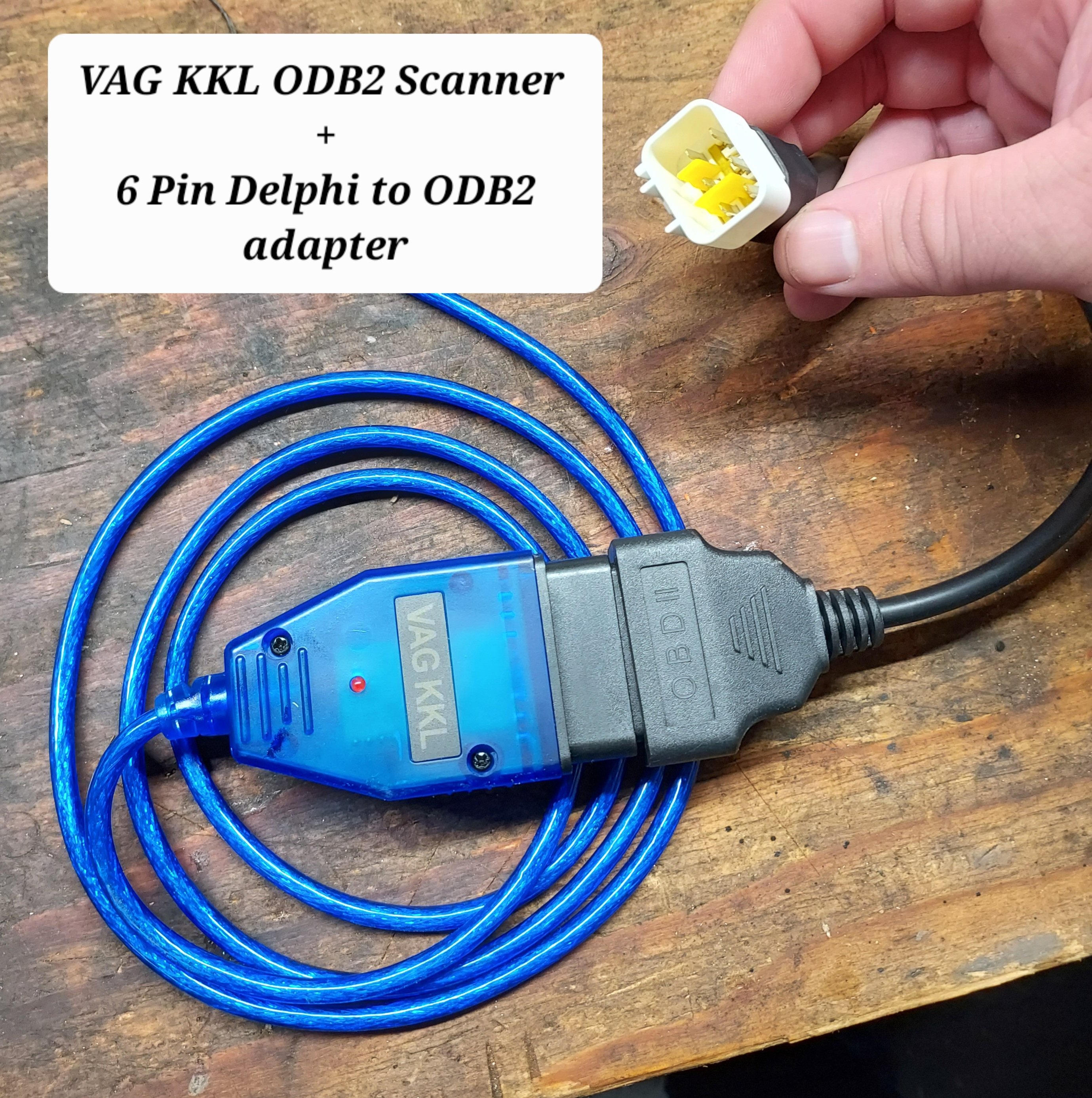
In order to connect with the ECU we need two cables. The first is a USB ODBII cable. HUD ECU Hacker’s documentation has a lot of different confusing options, but here’s what I went with and managed to get working, the cable is called “VAG KKL” it is a USB to ODB2 cable. It is available from a variety of sources for $10-15. The second thing we need is a “6 pin delphi to ODB2” adapter cable. It is also available for a similar price. In my case I ordered both from ebay, but there are other sources.
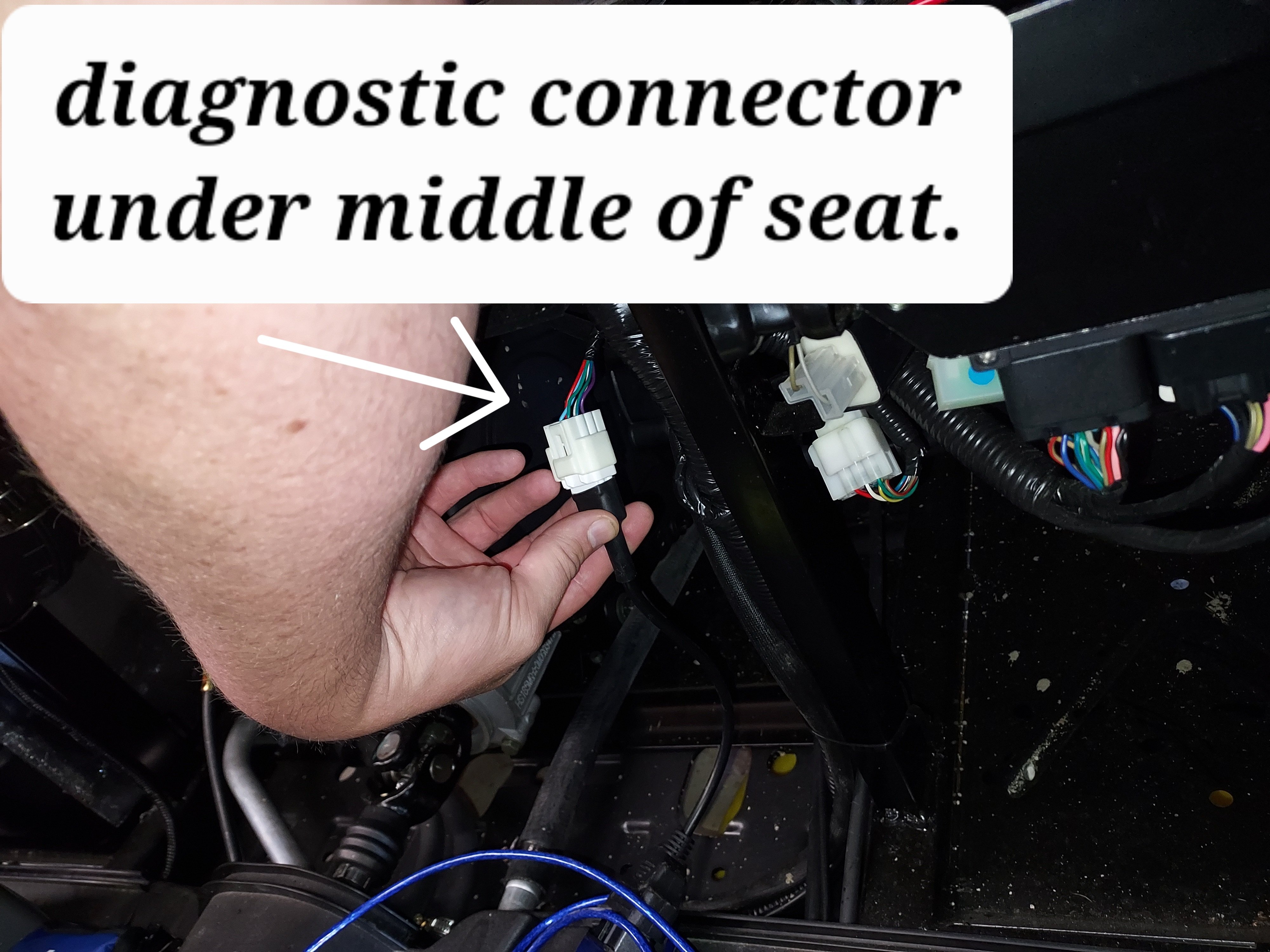
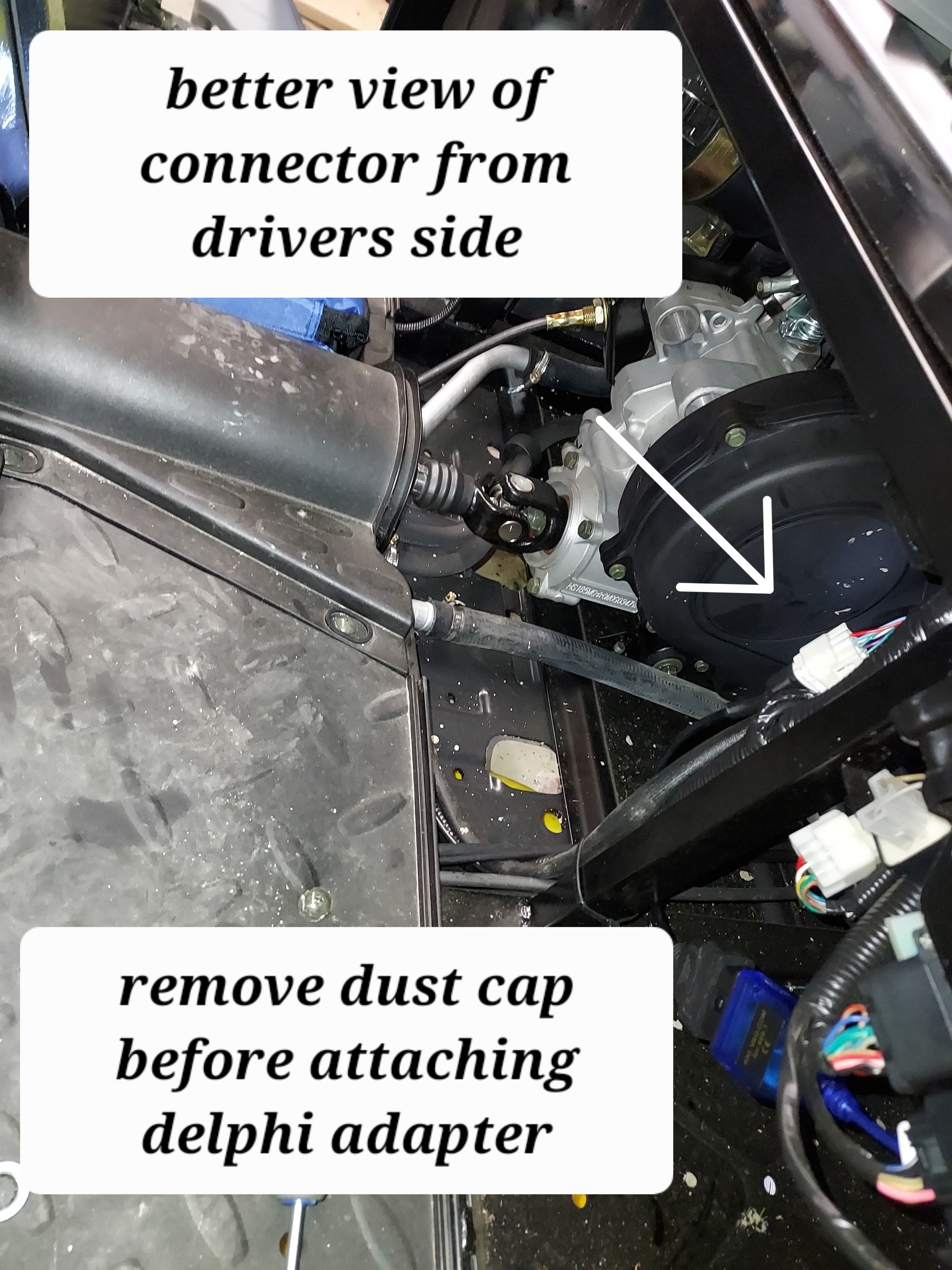
Once we have our cable in hand we need to find the plug it in on your machine. My personal rig is a Coleman UT400, but the wire location should be similar for all Hisuns. My cable was located under the middle of the seat area. Just inboard of the battery, where the main wire harness split loom runs.
The cable is a 6 pin (3x2) with a dust cap. Remove the dust cap and plug in the 6-pin end of the Delphi adapter cable.
Note: When I was done, I left the 6-pin adapter connected, and zip tied it so it now runs to in front of the battery for easier access in the future.
Next download and install HUD ECU HACKER DOWNLOAD
Open HUD ECU Hacker on your PC
It should prompt you to choose a driver to install. This particular cable uses the “CH340” driver (First choice on the menu) click to install, once installed hit the X in the corner to go back to the main page
Once the driver is installed plug in the USB Cable, and plug the ODB2 end into the 6 pin adapter. The red led on the adapter should light up indicating it has power.
Drop down and pick a com port on the main screen, it should show the VAG KKL adapter as a com port. Click connect on the main menu. It will pop up a bunch of fast scrolling text indicating it is connecting.
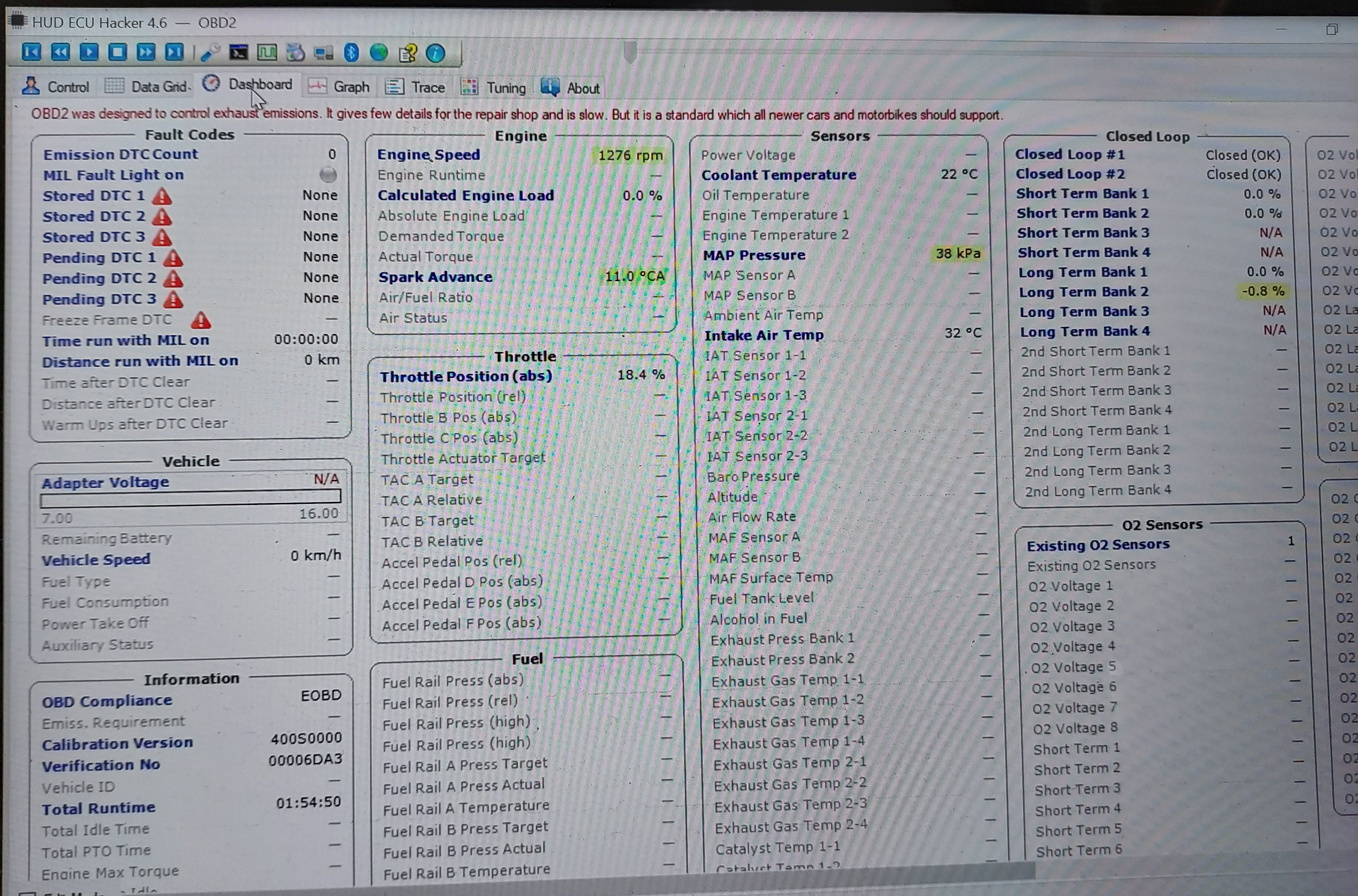
Once connected you can click through the various tabs to see different data sets.
The main menu also has the option to show fault codes, clear fault codes, reset the EPROM back to factory.
The other function that may be helpful is recording a log file. You can record a log while operating the unit, and come back later and replay it to try to better diagnose what is happening.
Within the various pages you will see the reading from each sensor. Sometimes a sensor reading will be off enough to cause running issues, but not enough for the ECU to realize its an issue. For example if the engine thinks it’s really warm, but its actually cold, it may not inject enough fuel to start.
There are also more advanced functions, like adjusting fuel mapping, but that is beyond the scope of this tutorial.
Full HUD ECU Hacker Documentation (Very technical reading)
If you find this helpful give me a comment below or a thumbs up.
-
3
-
2
-
-
This post will explain how to hook up your PC to the ECU of a Hisun/Coleman/Etc UTV to be able to read error codes & engine parameters for troubleshooting purposes.
This is applicable to all small engines using the Delphi MT-05 ECU. This should cover all fuel injected Hisun models, as well as various other Chinese FI engines, as the Delphi MT-05 ECU seems to be the favored ECU solution.
Even though we get actual engine error codes to display on the dash, sometimes we have “pending codes” (not yet confirmed by the ECU) or other intermittent issues that are hard to diagnose, for example a poorly connected sensor that may give intermittent false readings, or a sensor that’s putting out bad date, but not bad enough for the ECU to realize.
The setup requires 2 cables, which are available for around $25 combined, a PC with a USB port, and some charityware software called “HUD ECU Hacker”. This gives the same functionality as the $300 dealer code scanner for a fraction of the price.
In searching I found info about HUD ECU Hacker, but I have yet to see info anywhere about how to hook it up to a Hisun, so I took the leap and bought some cables, and made it work. I will show a step by step of how to do so in post two.
I will be breaking this down into 2 posts:
- Delphi ECU Info & Overview (This post)
- System setup & use
Delphi ECU Info (Skip ahead to the next post if your eyes glaze over technical details)
The Delphi MT-05 ECU was developed to allow small engines to use fuel injection. A fuel injection system requires feedback from various sensors to operate efficiently. This feedback allows the adjustment of ignition timing, fuel injection volume, etc to efficiently and cleanly produce the most power possible from a given engine.
The MT-05 ECU has a number of sensors that are required for proper functioning including; Coolant temp, crankshaft position, intake temp, intake pressure, exhaust O2, throttle position, as well as some other optional sensors that are used on more complex vehicles.
From the sensors the ECU adjusts: Fuel injector timing/pulse, Idle air control valve, and ignition coil
The Delphi MT-05 puts out diagnostic data, however it is not ODB2 like a modern car, where is where it gets tricky reading it. There are three options, there is an old 16 bit piece of software Delphi has that is not able to run on a modern computer, there is the motorscanner tool for dealers ($300), or there is freeware HUD ECU Hacker with the proper cables.
-
1
-
Since I've seen some questions on this I took some pictures and will provide instructions on a valve adjustment for the UT400. This should be the same for the 550's and other various Coleman/Hisun single cylinder models with the cylinder slanted aft.
I have seen several people ask of it is really necessary, and read several reports of valves being out of adjustment from the factory. My valves were .004" intake, and .010" exhaust with about 5 hrs on the machine. I've seen different numbers thrown around for factory spec, but I decided to go with 0.005".
This is called valve lash. What is is is a gap between the rocker arm and the valve then the camshaft isnt opening the valve. Why does it matter? If it's too large the valve doesn't open all the way, if it's too small the valve dosent close. This can cause valve damage (overheating) as well as loss of engine power (burned fuel is going out exhaust rather than pushing the piston dow).
Tools required : 5MM Allen wrench, 10MM box wrench, needle nose pliers, flat feeler gauge set, rags
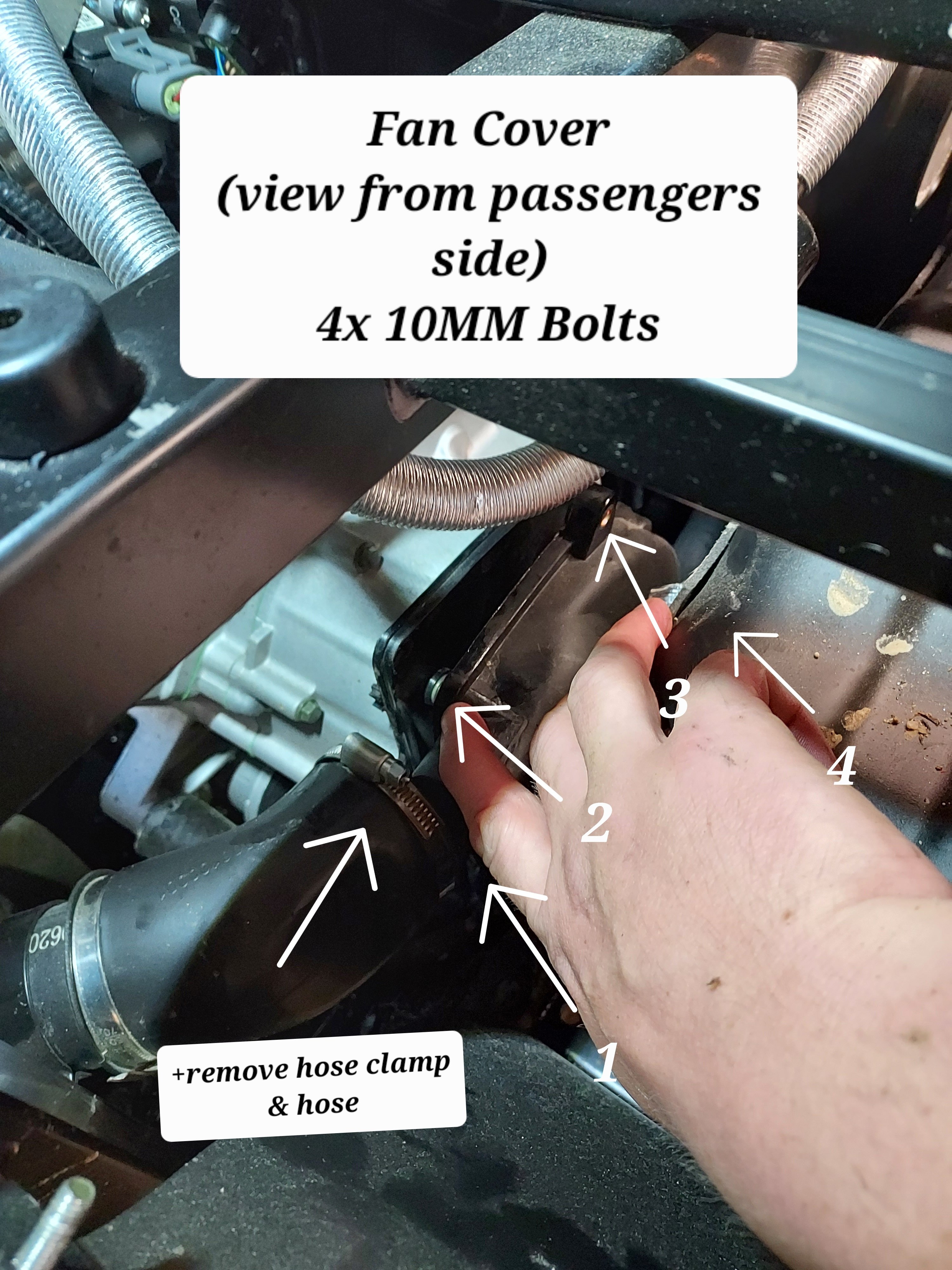
First you need to remove the fan cover on the passenger side. There is a cooling vent hose on the back side, remove the hose clamp and slide it off. From there there are 4x 10mm bolts holding the cover. The forward ones can be accessed from under the seat.
Next remove the spark plug from the drivers side. Carefully wiggle the spark plug wire off. Grip it as low as possible and give it a little twisting motion as you pull it off to help free it. Its a tight fit for a socket, but there is a sheet metal wrench in the toolkit that fits it. Unscrew the plug and set it aside. This allows you to spin the motor over freely with no compression to fight. When you reassemble this is a good opportunity to switch to an NGK iridium plug for better performance/less fouling DR8EIX)
Next you need to remove the intake and exhaust valve covers. The intake us the forward one. There are 3x 5MM Allen screws to remove. The Exhaust is the rear with 2x 5MM Allen bolts. Both covers have O-Rings instead of gaskets and are reusable. When you remove the rear be careful and use your rags as there will be oil that drips out.
Next up we need to spin the motor over to top dead center. Grab each rocker arm and give em a little wiggle up and down. Spin the engine over by grabbing the fan with your other hand. Spin the engine over until both rockers have some wiggle and are loose.
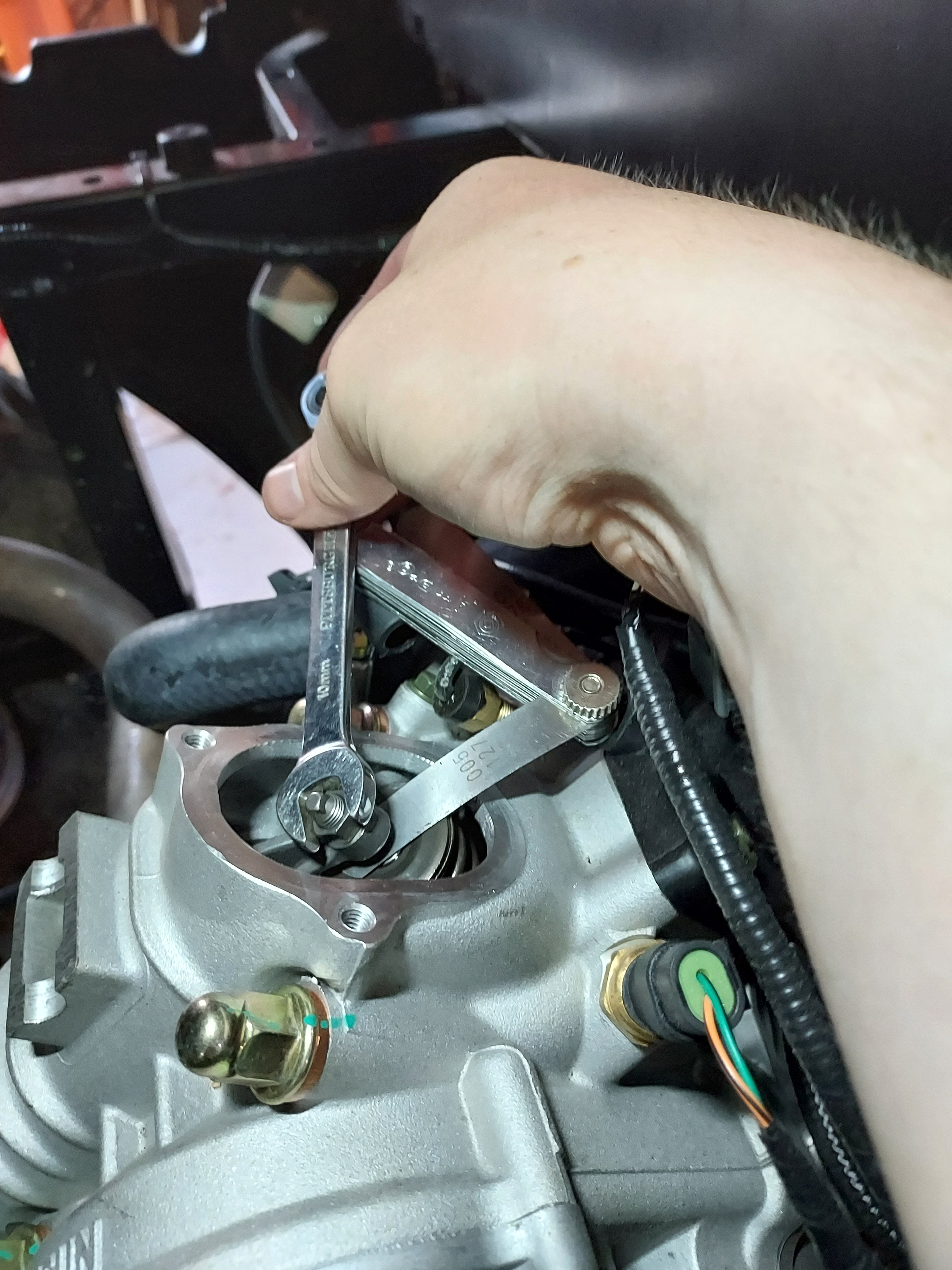
Once both rockers are loose slide the feeler gauge in like shown above. Try different feelers as needed to determine your starting spec. You should feel some drag but still be able to move the feeler without too much force.
If you need to adjust, use the 10MM wrench to slightly loosen the locknut, then with the correct feeler gauge in place, tighten the top square nut while wiggling the feeler in and out. Once you have it right you need to tighten the 10mm lock nut without moving the square head bolt. Once the lock nut is tight recheck the clearance.
That's it, button everything back up and make sure you have it all reassembled before running it again.
If you find this helpful give me a thumbs up or comment. If you have any questions or need more help let me know. If there's interest maybe I'll do some more of these
-
6
-
-
It had a little slack, I added a bit more just to be safe
-
1
-
-
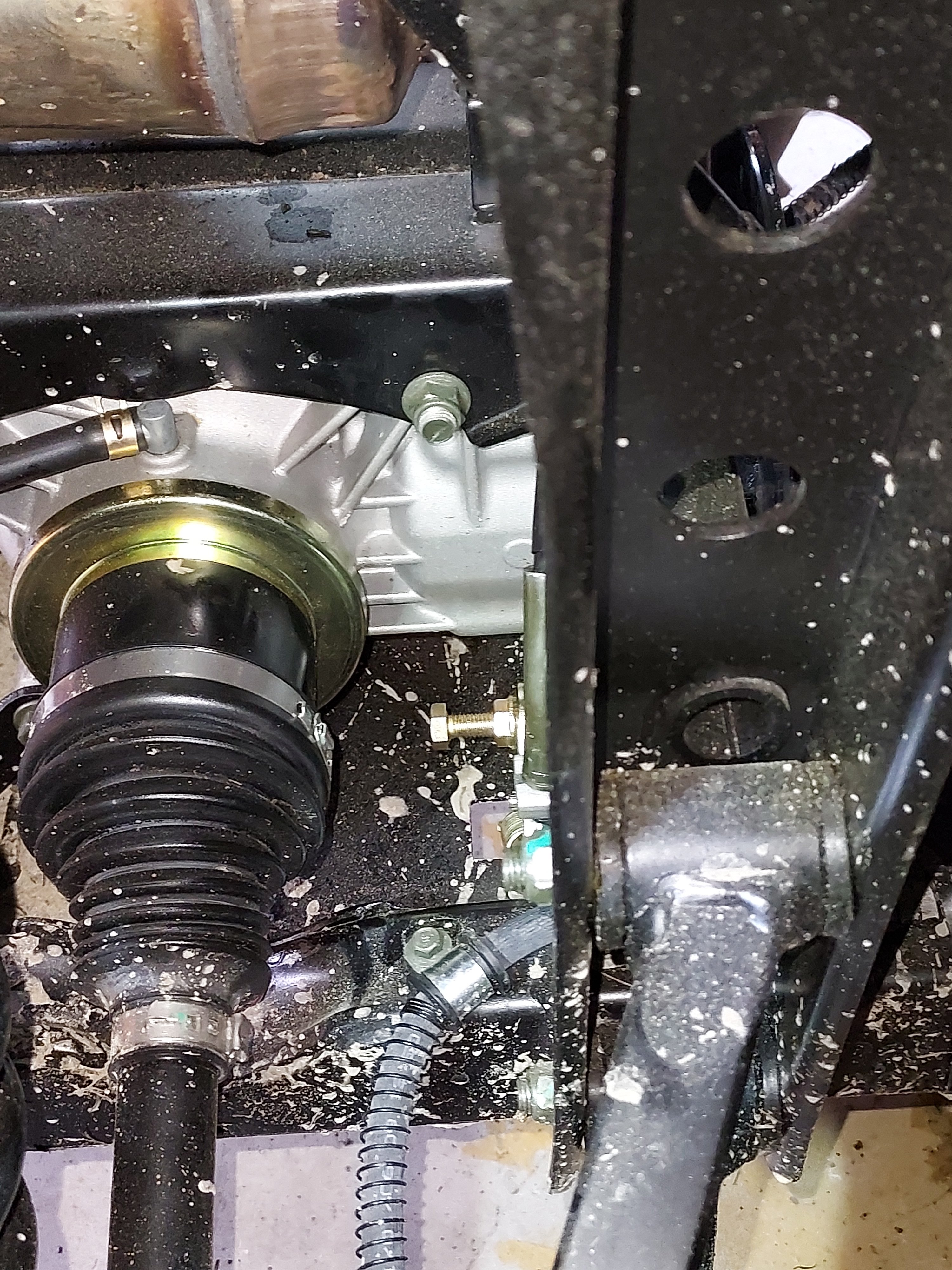
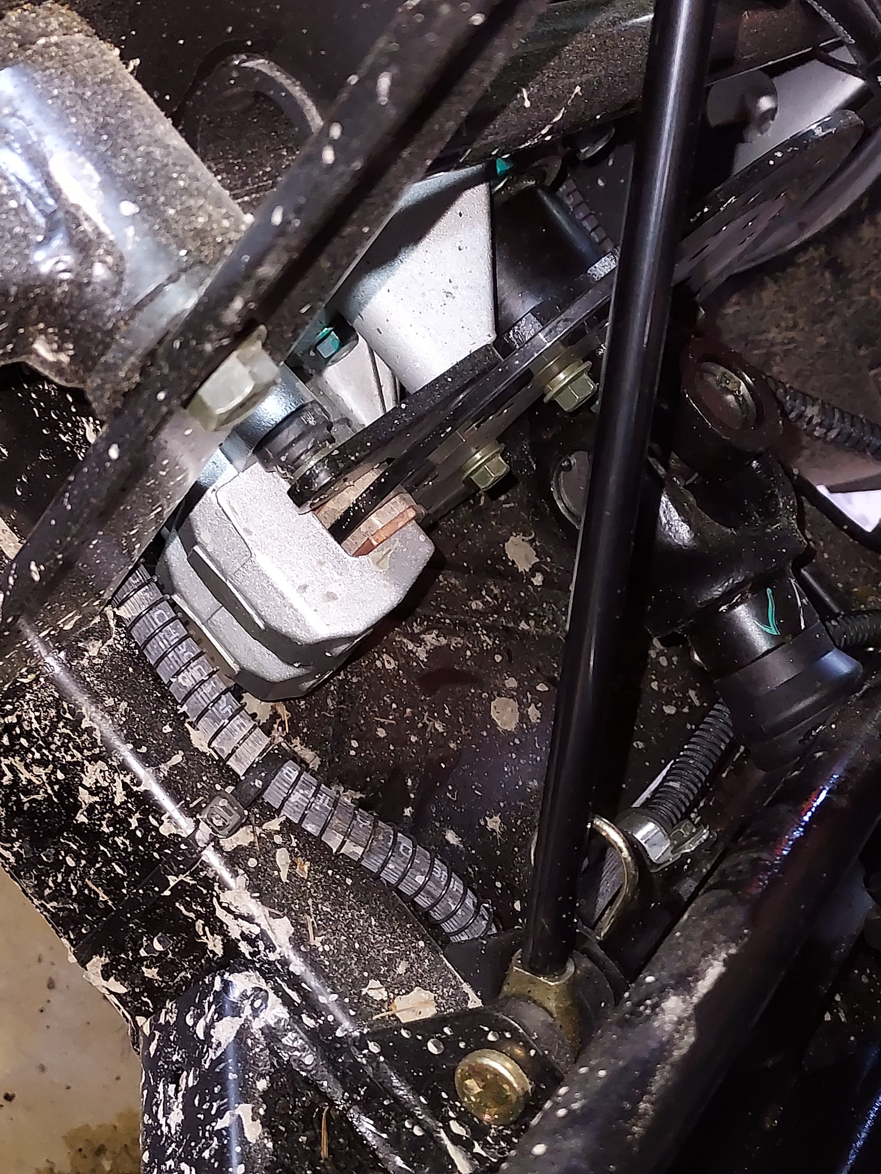
I was under the rig playing today so I decided to adjust the parking brake just to make sure it was ok, since I've read a couple people having them adjusted too tight from the factory.
First picture is the parking brake disc & caliper from the passenger side. Second picture is the adjustment bolt.
How it works: it's a cable operated disc brake with a locking pawl to hold it where you push the pedal to.
Procedure: The pad tightness is adjusted by moving the bolt in the 2nd picture in and out. When you tighten it it pushes the pads together. The extra nut on it is a lock nut.
Using a 13mm wrench loosen the lock nut. Back it off about halfway just so it's out of the way. Next tighten the bolt by hand until it stops. From there back it off about a half turn. Push the parking brake and make sure the pedal "locks up" before running out of travel. If it doesn't adjust the bolt slightly tighter and try it again. Once you're happy with the adjustment tighten the lock nut while keeping the bolt
stationary.
-
2
-
-
Ebay/Amazon actually have a fair number of parts especially "consumables" and normal wear parts.
For more parts & full diagrams :
https://alpha-sports.com/hisun_parts.htm?q=hisun-parts
There are a few weird things that might require going thru Hisun themselves
-
Hey Roy unfortunately there really isn't a practical of a serious hp gain way short of an engine swap. Realistically these engines won't hold up to making a lot more horsepower anyway.
There is a way using software to adjust the fuel map on the ECU but it would take specialized knowledge, and a lot of time playing with settings to really get anything out of it and best case you might be looking at a couple horsepower.
-
There are self adhesive rubber sheets with foil backing that are heat resistant and will help reflect the radiated heat you could try. As a bonus they also deaden noise. They are available for example, on Amazon, for relatively cheap.
I'm not familiar with that particular model/year but presumably like the other older models the cylinder slants forward under the driver's seat? If so it will be harder to deal with the heat due to the proximity of the cylinder. All the newer engines the cylinder slants backwards and is under the bed.
You also need to be careful what you block off for airflow around the engine because there are parts that require airflow to keep cool even on a nominally water cooled engine.
-
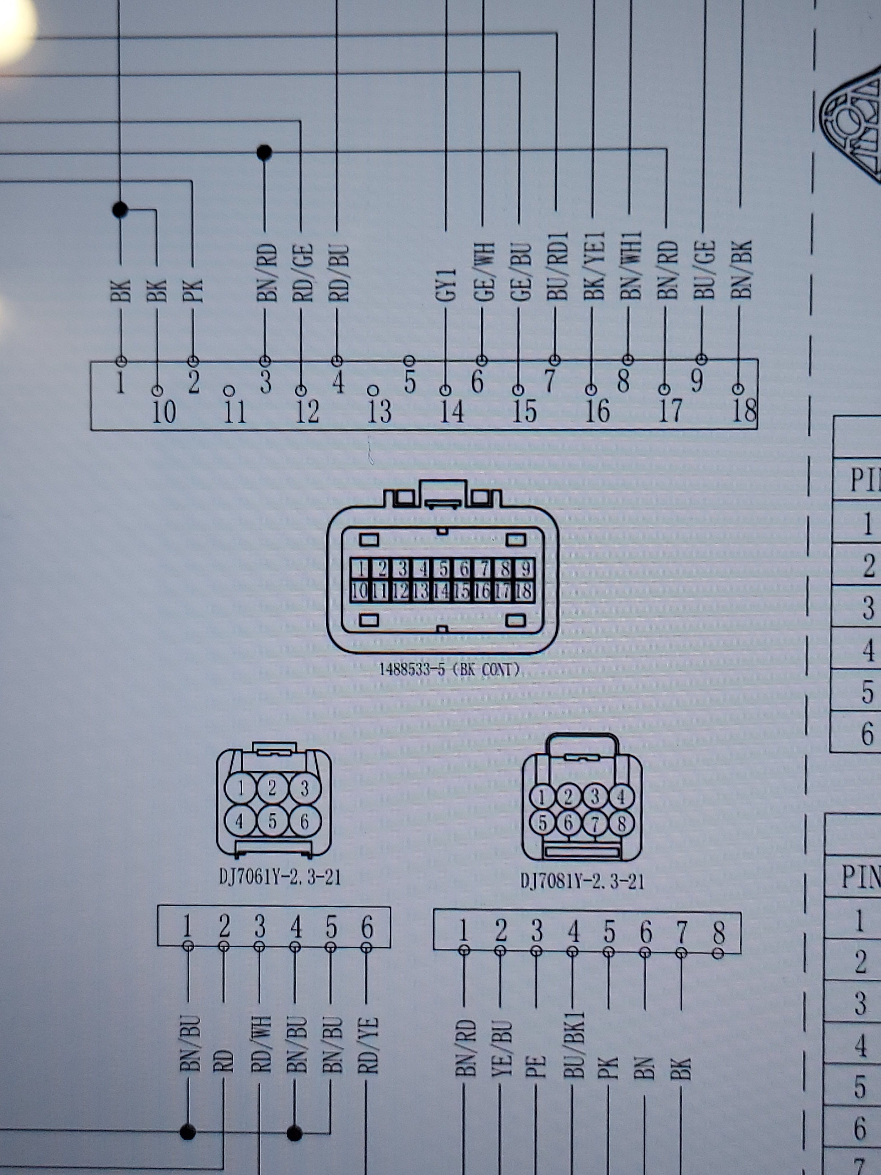
According to the big wiring diagram for the UT400 "F2" controls Brake/turn lights/parking drive alarm and speed limit.
So if your brake lights are working that fuse should be ok.
So from the fuse power goes to the flasher module, into the turn signal stalk and out to the flashers. Those wires are dk brown and dk green. The feed for the parking lights comes from the combo stalk switch but goes out the blue wire.(
The only place where this is all common is the black wire that runs from terminal 1 on the big connector on the fuse/relay box (see pic attached). That should be the ground to the turn/parking lights. I would check the continuity from the pin on the relay/fuse box to ground and also check with the lights switched on and key on and that wire disconnected there should be 12v between that wire and ground.

-
There are actually 5 disc brakes on these machines. 1 for each wheel and 1 on the rear driveshaft for the parking brake.
I've read several complaints of the parking brake one being too tight from the factory so I would check the cable and make sure there's a little slack when the parking brake is released.
If that is good I would jack up each corner Individually and spin the wheel to listen for noise and feel for dragging. That should help pinpoint where the issue is.
-
3
-
-
Lol that's another solution. Goodluck with this one!
-
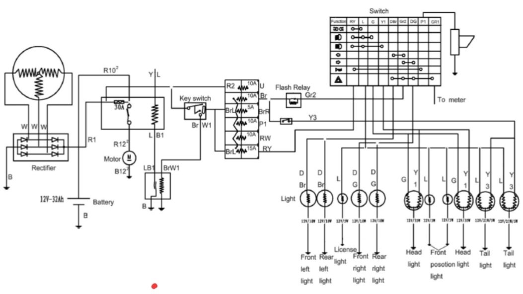
When the key switch is on you should have power to all the fuses.
You didn't specify a model. This is the lighting circuit diagram for the 400. The 550, etc should be similar if not identical.
If you don't get power to the fuses, and the batt is good
the keyswitch would be the first thing to check.


2012 hisun 500 power loss
in Hisun UTV SxS Forum
Posted
I would guess it's running lean and overheating.
Does it have an inline fuel filter?