


Kinarfi
-
Posts
2,186 -
Joined
-
Last visited
-
Days Won
37
Content Type
Profiles
Events
Forums
Gallery
Downloads
Community Map
Posts posted by Kinarfi
-
-
http://www.utvboard.com/topic/2915-front-suspension-heim-joints-ball-joints-etc/?p=16750
This is the post I think you want, May not of been the exact post you wanted, but here's a link to my Google drive photos
https://drive.google.com/folderview?id=0ByQAhs0e-yF9RTVaV0VMOEpjeWc&usp=sharing
-
I'm trying to see what I can get it for.
I'm still asking questions to see what i can do also.
-
$499, a bit much for me, even if it works, but after a few of the people I talked to, I think it will.
-
Wiggle, unplug and replug every connector, sounds like something may be loose, even thing that are plugged properly don't make good connection after some time and need to be separated and rejoined to clean the contact surface and make good connection. This includes relays and fuses. As you pull relays, look at the blades to see if there is any discoloring or signs of heat and look at the socket where the relay plugs into.
-
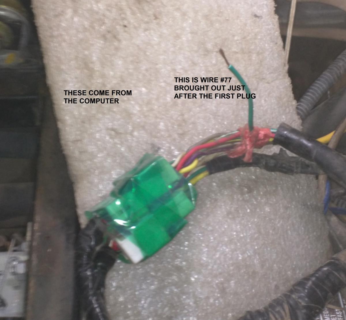
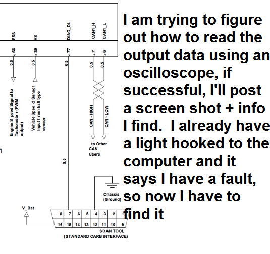
I found the wire I was looking for, it is brought out just past the first connector after leaving the computer, starts as white/green strip and then it is green after the first connector. I hooked my oscilloscope to it and started the engine and all I could see was some voltage spikes, I assume these are telling the OBDII reader it can request data from the ECU. So other than finding where to tie in a plug so I can plug in a reader, I didn't get any closer to finding what was causing my fault light to be on.
Here's some photo I took while finding the wire, I added text to each photo.

-
I have two automotive scan tools neither worked I talk to silver bullet and no limit Powersports and was told it's a cherry automotive specific tool you need and if I remember mine is right near the fuse box and even behind driver seat
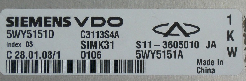
I've been all over the area behind the seat (and every where else) and haven't seen anything that looks like a plug. Can you post a photo? My ECU is a Siemens VDO, I wonder if they can tell me the codes.
-
I have two automotive scan tools neither worked I talk to silver bullet and no limit Powersports and was told it's a cherry automotive specific tool you need and if I remember mine is right near the fuse box and even behind driver seat
I've been all over the area behind the seat (and every where else) and haven't seen anything that looks like a plug. Can you post a photo? My ECU is a Siemens VDO, I wonder if I can contact them for the codes they used. will try
-
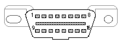
has anyone found the Vehicle OBD II Connector (front view) or installed or used one on their Trooper?
Thanks
Jeff
https://en.wikipedia.org/wiki/OBD-II_PIDs#Modes
-
Lately I've noticed a loss of antifreeze and when it was bad enough, I would run hot, and I noticed a dark build up on the same side as the filler. I removed thee radiator and sprayed it with soapy water to check for leaks and found all of tubes in the top 4 or 5 inches of the driver's side leaking at the header.
I had recently read that this could be fixed with J B Weld epoxy,http://www.stockcarracing.com/techarticles/scrp_0411_stock_car_radiator_repair/viewall.html
you build a damn with some tape and then mix up your epoxy and thin it with denatured alcohol and pour it on the fins and allow it to run in between the fins and then use a vacuum to try suck the thinned epoxy into where the leak is.
I prefer the long setting epoxy
http://www.utvboard.com/gallery/album/144-radiator-repair/
I am planning to see if I can move the spare tire from on top to the back and then put the radiator up on top, out of the dirt.
Also had to rebuild the fan shroud because the mounting holes were cracking up.
-
there is a DLA valve, page 109, that lets air past the butter fly, sound like it failed, there is also a idle adjustment screw, page 49, find it, use it,
-
what year?
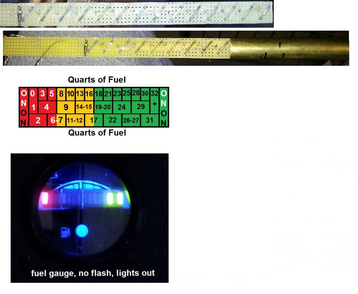
I think I still have my original sender of 5 or 6 reed switches, Or you could build one like mine. It has 14 reed switches and 16 LEDs, the 1st & 16th are always on 2 thru 4 are red, nearly empty, 5 thru 7 are yellow, less than half, and the last 6 are green, good to go. The brass tube is in the center of the tank and sealed so the circuit board & reed switches are dry. Down side is you have 15 wires running from gauge to sender.
-
What are you driving? What's the fuel gauge for?
-
Last time I replaced the Hiem joints and other joints, I applied a heavy coat of grease to all and then wrapped some polyurethane foam around the joint and secured that with some cheap electrical tape to keep the grease in and the water, mud and dirt out. Seems to be working pretty good.
-
 1
1
-
-
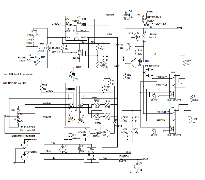
When I first started making an electrical power assist for my Trooper, I started with the drive wheel from a power wheels toy for kids and 2 relays, full power. That worked fairly well for a while, much better than no assist, then Lenny said, make the power out proportional to the torque in. I rejected that idea for a while, but became absorbed with the idea and I have made many models and designs and trials. I'm very happy with the controller I'm using right now and it can be built by someone with electronics knowledge. It is set to be very sensitive so it needs less input torque than most, it also has the remnants of an earlier trial set up that didn't get removed, so I added a switch that allows me to choose between sensitive and not so sensitive. The power unit is an older 170watt unit from http://www.superatv.com/UNIVERSAL-Kits-C1039.aspx, but has been up powered with a motor from Banebots, which can handle more power than I can safely feed to it with out burning up parts.
So if you have a power unit and no controller, maybe you can build one or have some one build one for you. I have attached the schematic, a spice file is available if you contact me, this program won't allow me to upload it
-
THUMBS UP, You ought try the sand dunes before they dry out also.
-
Will it start if you push it, & if so, will it start up after it warms up and keep starting until it cools way down? This, IMHO, indicates that your compression is down.
-
Crappy video of steering box play...
Hard to argue with that, crappy, looks like you need front wheel bearings, rock your tire like that and look for movement between the hub and the cv that goes to the axle. Lenny used to sell a fix for your play, but I think he quit making them, an alternative would by to put some shim stock between the top plate and the slider piece, maybe replace the top plate with a thicker plate or make it out of steel.
-
I run 35 PSI on my regulator, Hook a light across your fuel pump to monitor the voltage,
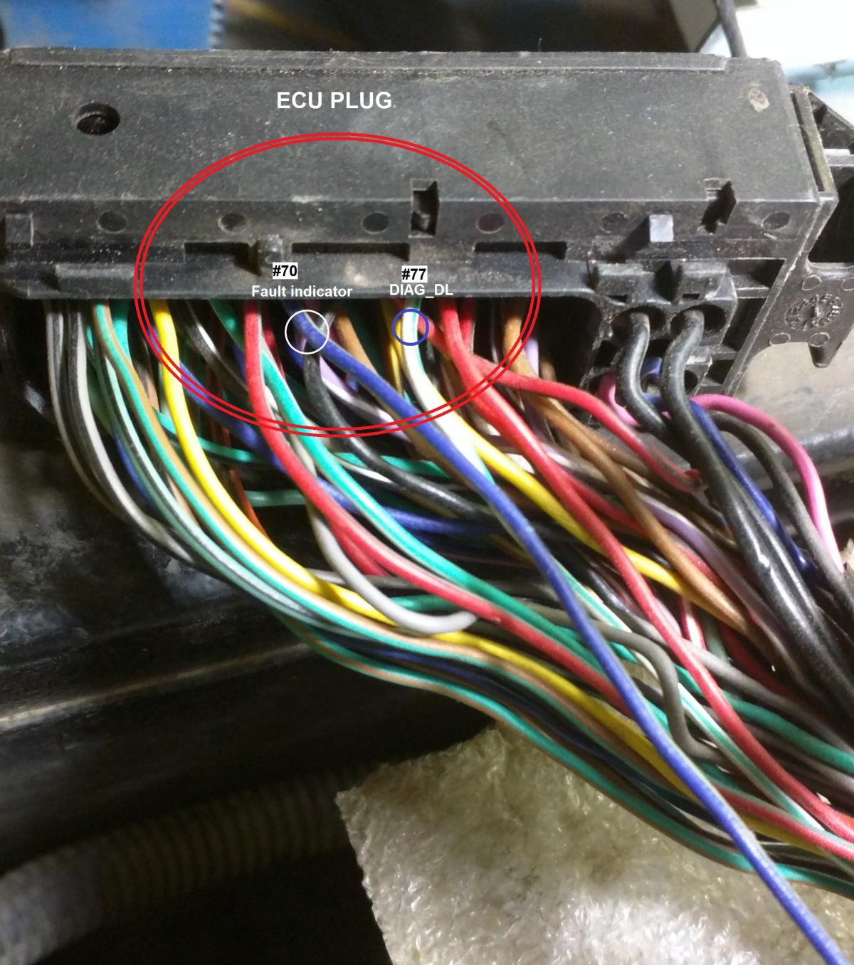
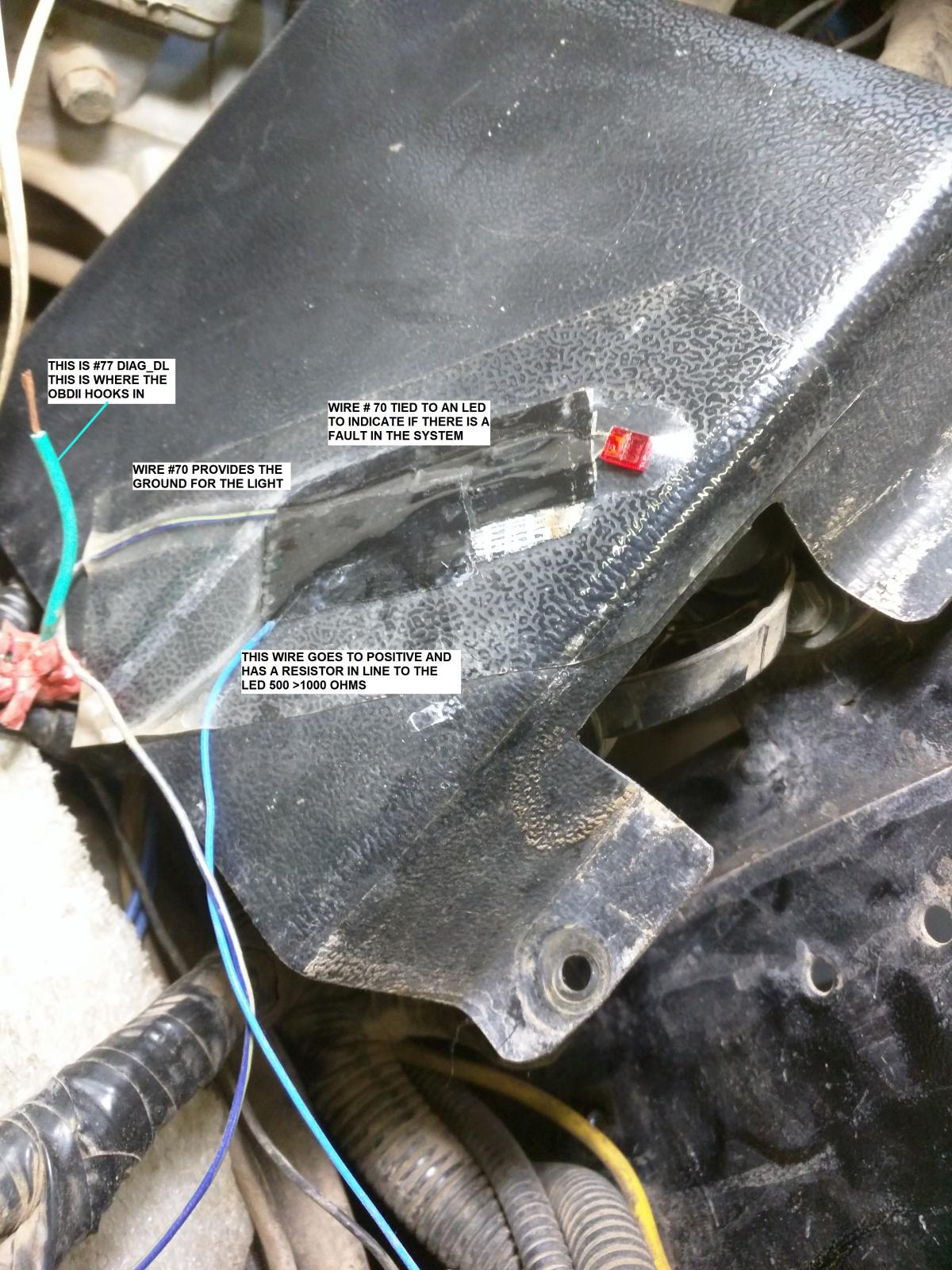
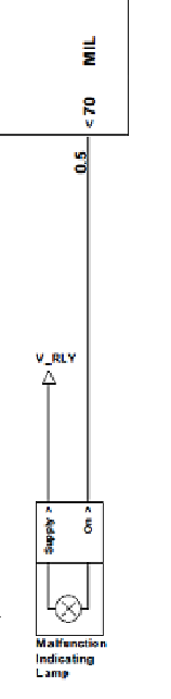
also, on the computer pin out. X1-70 - MIL - Mal-function Indicating Lamp Output could be hooked up to show if you actually have a malfunction. If you want to do that, just remember that pin X1-70 is a sink to ground, that means that 12 volts is supplied to a light and the light is grounded via X1-70 if there is a mal-function.
-
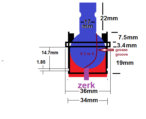
Is the slop in the ball joint or where the ball joint slips into it's pocket in the A Arm? If it's the ball joint, grind off the tack welds, take the top off, drill a hole for a zerk, take a file or Dremel and cut a few lines from top to bottom for grease channels and then screw the top back on and weld it, more than a tack, when you grease them, the pressure of the grease gun forces the ball down and it seals harder against to bottom and you can't put grease in, that's what the lines are for so make sure they go out to bottom. When you screw the top on, make it snug but not binding.
Tie Rod Dust Boot, Checker Auto#13566 as shown in Parts and Pieces thread. -
how many miles / kilometers do you have on that machine now.
http://www.mcmaster.com/#91458a122/=x5bz8amay help in the meantime.
-
Did you measure both sides of your fuel pump?
measure (IN +) to a good chassis ground, pump (IN +) to a good chassis ground, AND (IN +) TO (IN +)
-
-
http://www.utvboard.com/gallery/album/112-kinarfis-album-2008-t2-mods/
I added a few photos that I think my be related to your problem, schematics and computer pin out and my winch relay set up.
-
The winch relay gets real hot if used for an extended period of time because of the high wattage pull in coils. I got rid of mine and replaced it with 4 individual relays, I don't know if any major grounds or powers go through the relay system that would effect the fuel and ignition, but a tweak tightening and unplug and plug back in any connector you can find may restore what ever was lost due to corrosion or heat.
The schematic for the computer is in the pinned Parts, pieces and Information topic at the bottom, you can down load it.
Do you have a couple of volt meters? I will assume yes, hook one to each side of the fuel pump and turn the key on, if you read voltage on both meters, you've lost the ground, if you don't read voltage on either meter, you've lost power. try it and let us know what happens.

Bad Bad News for my Trooper T2
in Joyner UTV SxS Forum
Posted
I had my output shaft break also, here is a link to all the photos and information I gathered when I replace the shaft, there is some good info here, download it and unzip it.
Jeff
https://drive.google.com/file/d/0ByQAhs0e-yF9a3gwenpyc2IxZWM/view?usp=sharing