-
Similar Topics
-
 By Adrian Domingues
I have 31 miles on my new T-Boss 550. In order to start I put in nentural and the emerage brake on and push down on brake paddle, then trun ket and get nothing, with key still on I shift to reverase and the back to netural and it starts. Anyone know what is happening.
Thanks for your help
-
 By Sammy
Runs fine just putting around the yard. Get it out on the road and about a half miles it runs out of gas. Let it idle for a few minutes and it will run for another half mile and do it again. Replaced both fuel pumps and filter. Does anyone know if I can get rid of the factory fuel pump?
-
 By didgeridoo
Hello, All! I've decided to replace the traction batteries in my 2018 Sector E1 with a 48V Lithium set. They may be expensive, but I figure the Discovery Dry Cell are, too. I am not looking for the max driving range, as I have never received near the brochured range to begin with, but a good mix of charge/ get work done/ charge is what I am expecting.
I have settled on the 48V EAGL kit from bigbattery dot com. Each battery pack provides 30Ah. The kit ships with a charger, as well. The packs would be physically connected in parallel (using a busbar) to one another, maintaining the 48V voltage, but together would be able to provide the amp draw the buggy pulls when going up hill or towing a rake (rated 320 max continuous Amps). This is in comparison to the serial connection the eight 6V lead batteries. Each of the EAGL batteries looks to have its own BMS; am I correct in thinking I will have to use their included charger rather than (simply) changing the onboard charger to lithium mode? The chemistry of the pack is LiFe PO4, for what it's worth. I haven't torn anything apart yet (to diagram), so I am not sure how the dash will interpret the AMP draw, but the kit I am looking at includes a dash mounted charge indicator.
If anyone has completed a similar conversion, do you have any tips? Specifically, how did you remove the original batteries, and how did you secure the new ones? I am guessing that almost any change from the stock batteries would involve at least some modifications. Any tips would be appreciated, especially things I may have failed to consider. Thanks!
-
 By Firewalker918
I have a 2021 UV34XL and I am kind of looking to change it up from the orange wheels and maybe do a wrap? Please share photos of any XLs that has been modified to look better and any seat covers recommended.thanks
-
 By Debbie Hogan
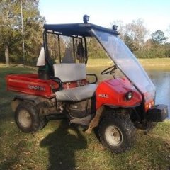
I realize this part is discontinued but im trying to find this exhaust pipe fir my dads 550. His brother who has since passed bought this mule for my dad who is now 90 and he is trying to fix everything on it. I'm willing to take a used one. A new one would be great if someone still had in stock. I'll take anything as long as it is in workable condition. If anyone has any ideas for me im open to hearing them. Thank you so much.
Debbie fm Texas
-


Recommended Posts
Join the conversation
You can post now and register later. If you have an account, sign in now to post with your account.
Note: Your post will require moderator approval before it will be visible.