-
Similar Topics
-
 By rdc
I have a 2007 Joyner 1100 sand viper and before it even get's to where the thermostat opens up the oil pressure get's so low I have to shut it down. What could fix this ? I thought about adding an oil cooler with fan, thicker oil, or removing the thermostat. Any advice?
-
 By AlphaSerenity
Hello,
Before I invest $10k+ into a brand new UTV for the farm, I want to get my feet wet with a fixer upper and learn the mechanical side of things. I acquired a 2022 Hisun Axis 500 (Lowes-specific model) from an auction for $500. It has only 200 hours and 120 miles on the engine. It looks like the previous owner used it for ranch work and didn't drive it on trails, deep water/mud, or anything too crazy.
While it runs and moves, it has some problems. It struggles to accelerate up any incline in high and low range and sometimes stalls when I let off of the throttle or change gears. When I apply throttle in neutral, it sounds like it is struggling for fuel/air and pops. When I decelerate, there is a grinding sound coming from the clutch, which I've read to be related to the one way bearing and is semi-common. The last thing I've observed is sometimes the speedometer display sometimes will show a much higher value for a few seconds after barely touching the throttle. Based on the documentation, if a problem is detected from the sensors, the instrument panel display should have an error code rendered on the screen in place of the time, but this isn't happening. Here is a video showing some of these issues (engine is exposed with console removed):
https://www.youtube.com/watch?v=FFAkO5TaGps
Here is another video of the clutches in action:
I've done some research, but information on this specific unit and sister units is limited. There does seem to be transmission and clutch issues reported. I still need to check into the head gaskets. I don't have the equipment to test compression right now, but I do plan on ordering what is needed soon. I do have an order in place for some cables to read the diagnostics from the computer. There is a shop two hours away from me that works on Hisun products, but I am hoping the problem can be identified and is something within my ability to handle. Below is what I've already investigated. I am leaning towards the primary clutch needing replacement right now.
After getting it home and unloaded, I did the following maintenance/checks to it prior to operating it further:
Changed the engine/clutch oil (and filter) and gear oils using manufacture recommended viscosity Changed the air filter and checked for cracks in the air intake flow. Verified good suction. Cleaned the throttle body Changed the spark plug and verified the gap was within spec (0.6-0.7mm) Changed the coil and coil wire Changed the fuel lines, fuel injector, and verified the fuel pump was outputting the correct initial prime pressure for ignition and continuous pressure after ignition. Also completely emptied the fuel tank and made sure octane 91+ fuel is being used per manufacturer specs. Ran seafoam through system too. Cleaned the spark arrester and verified no cracks or gaps in the exhaust flow Changed out the O2 sensor Checked all wired connections to ensure they were secured and no breaks were visible Checked the belt for tightness and for any signs of wear and tear Verified 4WD and the differential lock function as expected - still hesitates and struggles uphill Verified the fan gears in the shifter are not corroded and working as expected ECU was reset after replacing sensors and fuel-related parts
Thanks!
-
 By jertex
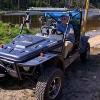
I bought a 2017 Stampede 900 last fall that was new, old stock with less than 5 hours on it thinking that I would be getting a relatively trouble free UTV as compared to buying a used Polaris or CanAm, or Honda, etc. It's been a little quirky, but reliable. What I thought was just a minor issue with this model, the difficulty in shifting between R, N, L, H, etc., was just a characteristic of this model is now a big problem. I had to climb two very steep trails to get to the upper meadow of our hunting property, which seemed to stress the UTV more than usual since I was carrying some lumber to work on a platform for a hunting blind, and when I went to shift into park, I felt something give and it would not shift out of low, but it did move up into high gear. I couldn't get it to shift at all at that point and the shifter felt mushy for lack of a better word. I was able to get it down to the lodge and when I investigated, I discovered that the straight, metal tube portion of the shift cable had bent to almost 90 degrees (see pics). I'm positive that it had already had some deformation that had happened previously and it had the right amount of resistance to bend to the point where it was unusable.
I have two questions:
1. I suspect that there must be some other issues that makes this UTV difficult to shift, and I'm wondering if this is a common problem and if someone could enlighten me on what could cause this to be difficult to shift?
2. Have any of you had this happen and if so, how difficult is it to replace the shifter cable?
Any other advice is welcome, this is the first UTV that I've ever owned, so I don't know much about working on these or maintaining them. I'm relatively capable when it comes to working on my own vehicles in general, and I'm not afraid to take things apart and get my hands dirty.
Thanks in advance for any insight, I'll be traveling most the day so I won't get a chance to look at replies until this evening.
-
 By OBL
program will open in old Bud program only/ but will not go in BUDS 2 to let use program ECU problem working on has new engine/ new fuel pump/ injectors/ lines/ sensors/ crank sensor maps/ and new throttle body and injectors. machine starts runs a minute dies/ on 3 rd try says key not recognized /we put other key in and same thing happens/wait 10 minutes, you can go again/ is there a back door in the program/ also might mention unplug temp sensor and map sensor , it will run a few minutes longer / then die again.
-
 By Nick Varnes
So I have a Bennche Bighorn 500 that I bought used a couple years ago. Was working fine until this winter when I was plowing and I think it drained the battery. And had a difficult time starting and staying running. Idle seamed really low, and would only stay running if I pushed on the throttle. So I changed the battery, and the acm valve, fuel filter and spark plug it will start up and surgery to 3k rpm but comes back down and dies, unless I give it throttle. I am getting fairly good amount of fuel from fuel pump. It does spit at stutter right before it dies. What should I try next?
-


Recommended Posts
Join the conversation
You can post now and register later. If you have an account, sign in now to post with your account.
Note: Your post will require moderator approval before it will be visible.