


Leaderboard


Popular Content
Showing content with the highest reputation since 04/28/2023 in all areas
-
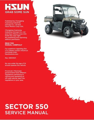
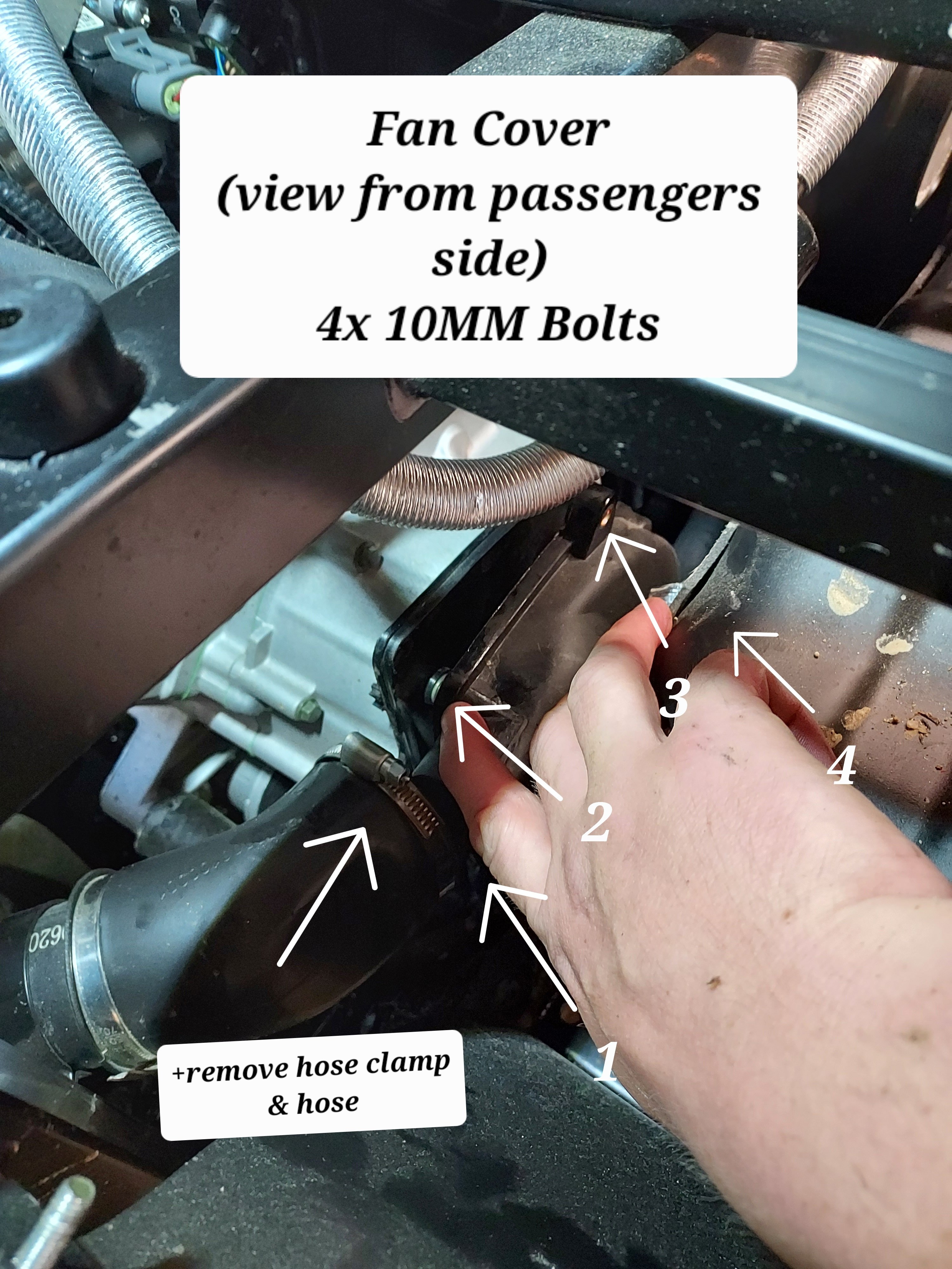
Since I've seen some questions on this I took some pictures and will provide instructions on a valve adjustment for the UT400. This should be the same for the 550's and other various Coleman/Hisun single cylinder models with the cylinder slanted aft. I have seen several people ask of it is really necessary, and read several reports of valves being out of adjustment from the factory. My valves were .004" intake, and .010" exhaust with about 5 hrs on the machine. I've seen different numbers thrown around for factory spec, but I decided to go with 0.005". This is called valve lash. What is is is a gap between the rocker arm and the valve then the camshaft isnt opening the valve. Why does it matter? If it's too large the valve doesn't open all the way, if it's too small the valve dosent close. This can cause valve damage (overheating) as well as loss of engine power (burned fuel is going out exhaust rather than pushing the piston dow). Tools required : 5MM Allen wrench, 10MM box wrench, needle nose pliers, flat feeler gauge set, rags First you need to remove the fan cover on the passenger side. There is a cooling vent hose on the back side, remove the hose clamp and slide it off. From there there are 4x 10mm bolts holding the cover. The forward ones can be accessed from under the seat. Next remove the spark plug from the drivers side. Carefully wiggle the spark plug wire off. Grip it as low as possible and give it a little twisting motion as you pull it off to help free it. Its a tight fit for a socket, but there is a sheet metal wrench in the toolkit that fits it. Unscrew the plug and set it aside. This allows you to spin the motor over freely with no compression to fight. When you reassemble this is a good opportunity to switch to an NGK iridium plug for better performance/less fouling DR8EIX) Next you need to remove the intake and exhaust valve covers. The intake us the forward one. There are 3x 5MM Allen screws to remove. The Exhaust is the rear with 2x 5MM Allen bolts. Both covers have O-Rings instead of gaskets and are reusable. When you remove the rear be careful and use your rags as there will be oil that drips out. Next up we need to spin the motor over to top dead center. Grab each rocker arm and give em a little wiggle up and down. Spin the engine over by grabbing the fan with your other hand. Spin the engine over until both rockers have some wiggle and are loose. Once both rockers are loose slide the feeler gauge in like shown above. Try different feelers as needed to determine your starting spec. You should feel some drag but still be able to move the feeler without too much force. If you need to adjust, use the 10MM wrench to slightly loosen the locknut, then with the correct feeler gauge in place, tighten the top square nut while wiggling the feeler in and out. Once you have it right you need to tighten the 10mm lock nut without moving the square head bolt. Once the lock nut is tight recheck the clearance. That's it, button everything back up and make sure you have it all reassembled before running it again. If you find this helpful give me a thumbs up or comment. If you have any questions or need more help let me know. If there's interest maybe I'll do some more of these
 4 points
 -
Hello to anyone who reads this. I am Jon and I own J&M Outdoor Power, a very small, small engine repair shop. I was approached by Coleman about 6 months ago to become one of their Warranty Centers. I recently received 3 different UT400's and a UT500 all with similar issues. These units range from 2 months to 2 years old. Customers state that the unit(s) was/were running fine, then heard a pop and a loss of power, two would no longer start. The two that would run would not achieve normal operating speed (around 20mph I would say) without redlining the RPMs. I quickly found that the Valve lash on each unit had become too large on some(both intake and exhaust) and too tight on one(just intake). After setting the gaps to .005(I found multiple different people suggesting bigger and smaller gaps, but no definitive Coleman Spec number yet) every unit starts, runs, and achieves top speed without issue. I don't know how many others have come across these issues, and I wanted to get something out on the web for others in the same predicament. Please let me know if you have had similar issues. Edit: I realize that this will not be a fix all solution for this issue, as the oil level and condition should be verified before moving to the valves. Many times improper oil conditions will cause valve lash to change. These units all have good oil and proper oil changes.3 points
-
Are you talking about an electric heater? if yes its likely too much current. There might be 10 amps of available current coming out of the rectifier that isn't already claimed by the ECU and factory lights. 10 amps @ 12V = 120 Watts, which is about what an electric heating pad runs. If you're talking about a fan for a engine coolant based heater it's probably ok. If you have accessories and the running voltage is below 13.5V you have too much stuff attached. If the battery light comes on it means the battery is actively being discharged while running. Stator based charging systems on these things and tractors etc are really meant to power the ECU and factory systems not to provide a lot of extra power for other stuff, it's not like the alternator on a car.2 points
-
happy new year!2 points
-
The main trick is tilting the front end up. Block the rear wheels and jack up the front end at least a foot. A convenient ditch works well also.....rear wheels in a shallow ditch. The head bleeder screw should be opened. With the engine NOT running, almost fill the radiator (leave some air to avoid a mess) and burp (squeeze the lower hose line before the metal tube at the engine base passenger side floor area). Watch the radiator and the the bleeder. With the radiator "higher" than the head bleeder, the air should be bled and coolant dribble out. Close the bleeder and refill radiator (your clue you displaced the air with coolant) and start the engine. Burp more while running and if you get the circulation going the hoses will warm up. More bubbles should surface at the radiator filler neck. Shut off engine. Open bleeder and release any air in the head. The puke jug needs to be filled about an inch above the full cold line. Use a shop towel as a "seal"and use an air nozzle to SLIGHTLY pressurize the puke tank removing the air from the tubing line to the radiator neck. Then the radiator starts to overflow, a third hand can install the radiator cap. Run the engine and determine the head and hoses are at the close to the same temperature (as in warming up) through out the system. IR temp gun....fairly cheap now....can get real numbers. Scan the radiator, hoses, cylinder and head.....if all close you are done. Recheck fluids when done riding. Recheck the bleeder and top off the puke jug as required.2 points
-
From the look of the picture on the post, I can think of a couple things2 points
-
Its' not a car, this is a motorcycle engine with a small stator charging system. You can't expect to run high wattage accessories like a heater or huge light bars on these things . That will overwhelm the charging system, drain your battery an stop your engine. Could damage the charging system and voltage regulator too. You only have about 10 amps extra to run any accessories including lights.2 points
-
My dealer gave me an electronic version of the service manual and I have sent it to Kingfish. I will see if it will upload here for others to use. I'm not sure if there is a more appropriate way to do this, let me know if there is.. 2015-2017 Service Manual - Sector E1.pdf2 points
-
my Hisun in my Massimo , sold by Tractor Supply, assembled in Dallas, say Made In China on every part of all of it .. Altho it now has multiple Yamaha parts mixed in. lol2 points
-
https://motorcycledoctor.com/wp-content/uploads/2021/08/Valve-Adjustment-HiSun-2.pdf This should do it.2 points
-
Yeah, I adjusted mine multiple times without any luck. I had extended the shifter rod, as mentioned on this board, as well as some videos I watched, and that resolved the shifting issue. Now, after it slips into forward or Reverse, it never slips out. PS: If you go this route, remember to readjust the cable to compensate for the extended shifter. I had to do the adjustment an couple times after extending the shifter and then the problem was resolved.2 points
-
I finally found a service manual in stock and was able to make the adjustments per the specs!2 points
-
Problem was using cheap eBay injector. Bought quality one and hot pipes went away. Running like new.2 points
-
Buddy, I've been using that phrase a whole lot lately.2 points
-
Massimo MSU500 won't shift to low I would check the shift linkage. Adjust it make it a little longer, if it is not long enough it won't shift to low2 points
-
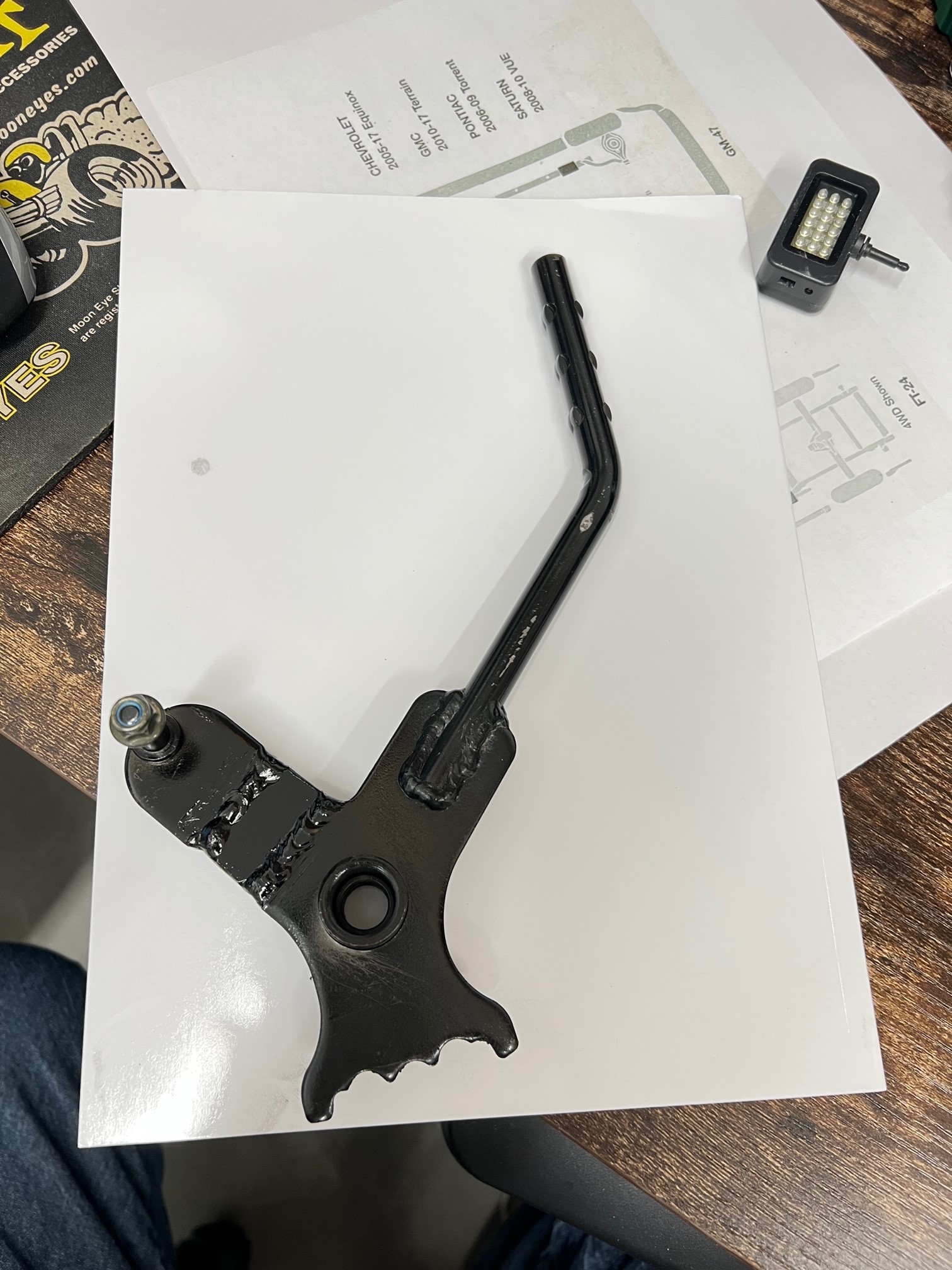
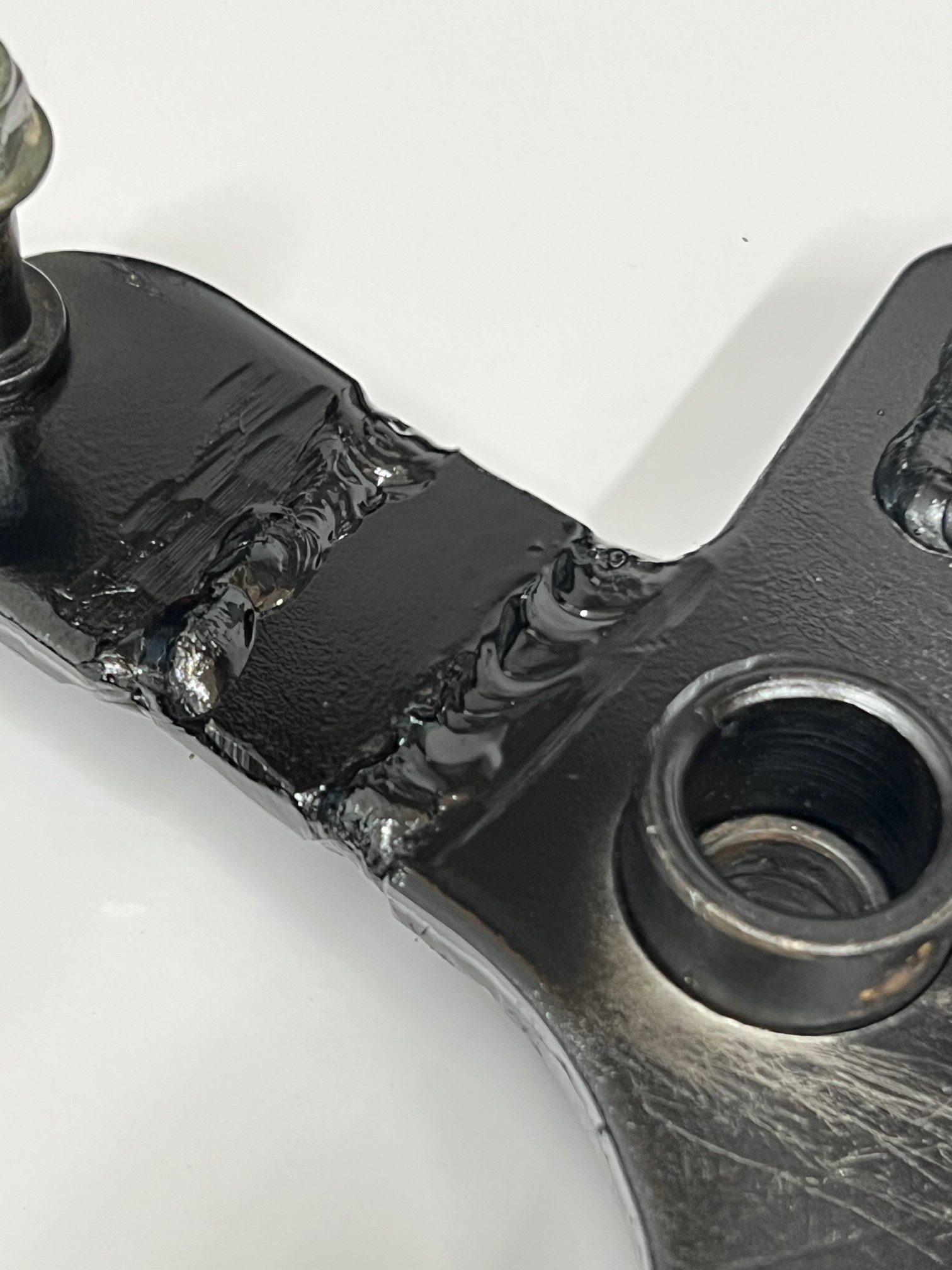
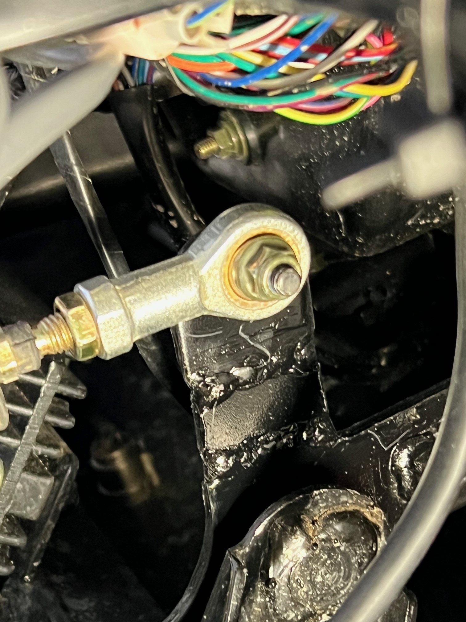
Hello again! I now have a pretty good running Coleman UT400 after a top end rebuild, wet clutch rebuild and a repaired crankcase... ! It plows snow great, but I was also having the jumping out of gear problem, mainly reverse, but a couple times out of forward. I would quickly place it in N and then let the engine idle down and shift again. This worked most of the time. I did some research and found that some have modified the shift linkage. The problem with just adjusting the shift cable is that it really NEEDS more throw, not an adjustment. From what I've read and viewed on the Internet, the linkage arm needs to be about 3/4" longer to gain more throw in both directions. On YouTube, the guy had to remove the shift linkage hole trim and notch the side of the dash to get the shift linkage off the pivot pin. BUT this is NOT necessary. When the "E" clip has been removed and you fish it out of the firewall somewhere, the shift lever is now loose. I had to pop the top of the shift knob off, remove the retaining screw and then heat the lower portion of the knob to get it to come off the lever. Once you have the shift lever loose, push it towards the right to slide it off the pivot shaft. But it won't come off just yet. Use a small pry bar/screw driver and slide the nylon flanged bushing out of the left side of the lever. This lets the lever slide off and get into a "loose" condition and it will twist and come right off without removing the dash trim, that could be a bugger to get back on correctly. Once the lever is off, press out the other bushing so when you're welding on the linkage arm, you don't melt the bushing. I found a piece of scrap metal the same thickness as the lever arm, just over 1/8" thick, close to 3/16". I cut my arm and beveled the edges for better welding. I added a piece just over 5/8" long and kept about a 1/16" gap between the arm and the new piece. Once welded on bother ends, it adds up to just about 3/4" or so. I reinstalled the lever after painting it and did an adjustment on the cable. By the way, it's easier to remove the cable from the bracket on the frame. This gives you more clearance to maneuver in that area with your hands. ALSO, you will need to get a 12" adjustable wrench and slide it over the cable mounting bracket and tweak, to the front, the steel so the cable is pointed upward a bit to now realign with the new longer shift arm lever. There's more than enough metal for the tweak and it will line up perfectly. I now bottom out the shifter on the transmission BEFORE I run out of throw on the shifter... I've tested it just a bit so far and it shifts much better with the longer throw. One of the Coleman authorized repair facilities said that he worked with Coleman to get a new part that's longer by 3/4". He's modified a few and it works perfectly for him. Just doing the cable will just short you on the other end. Here's some pictures of my modified shift lever etc.
2 points
-
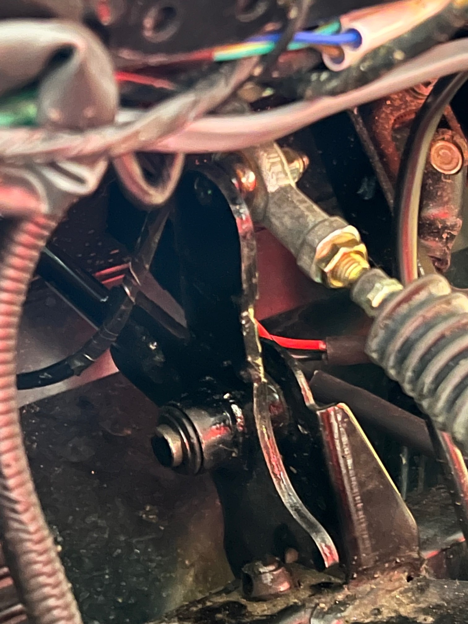
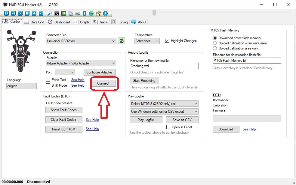
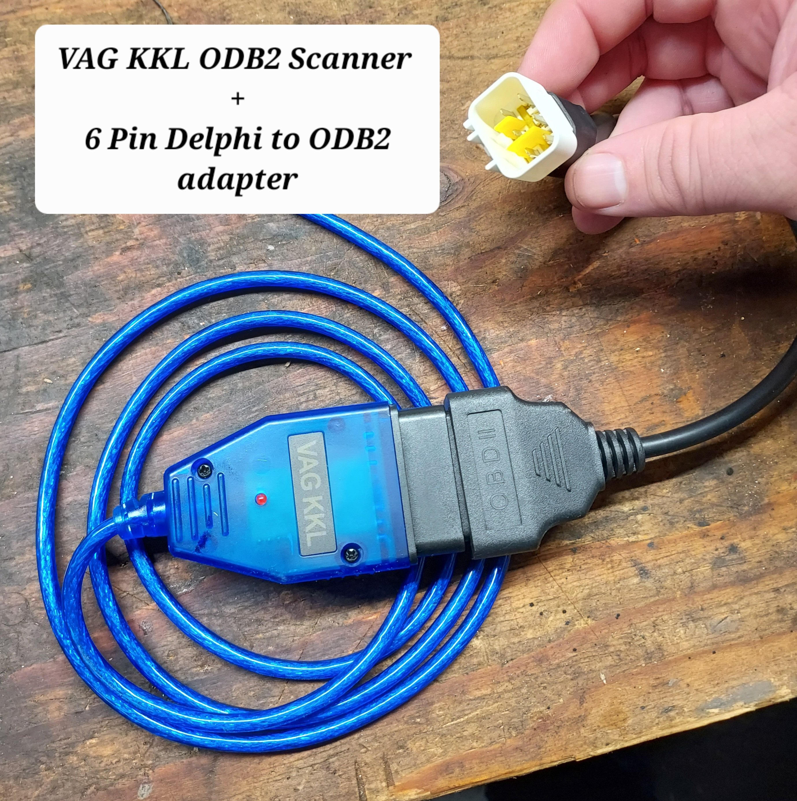
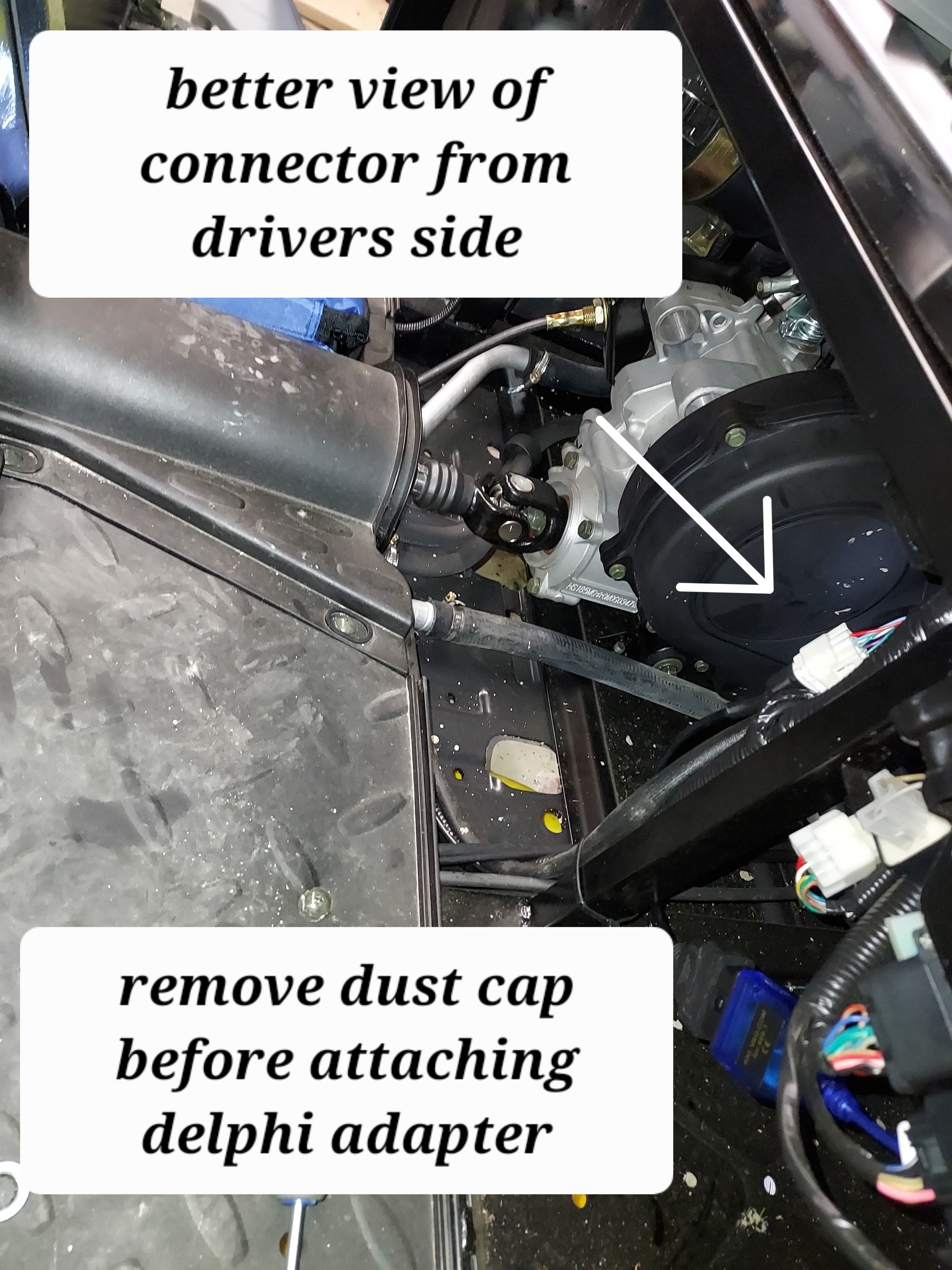
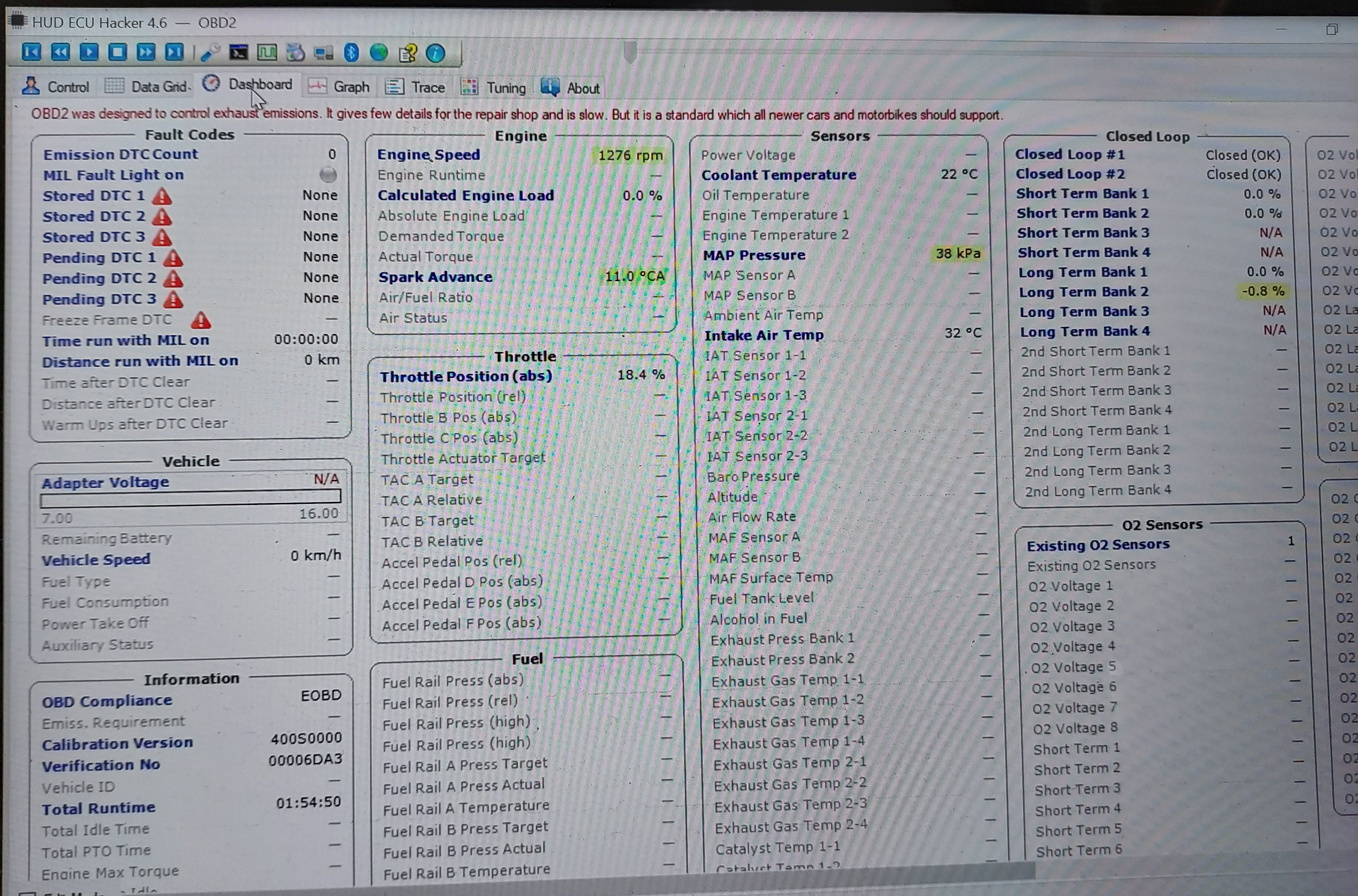
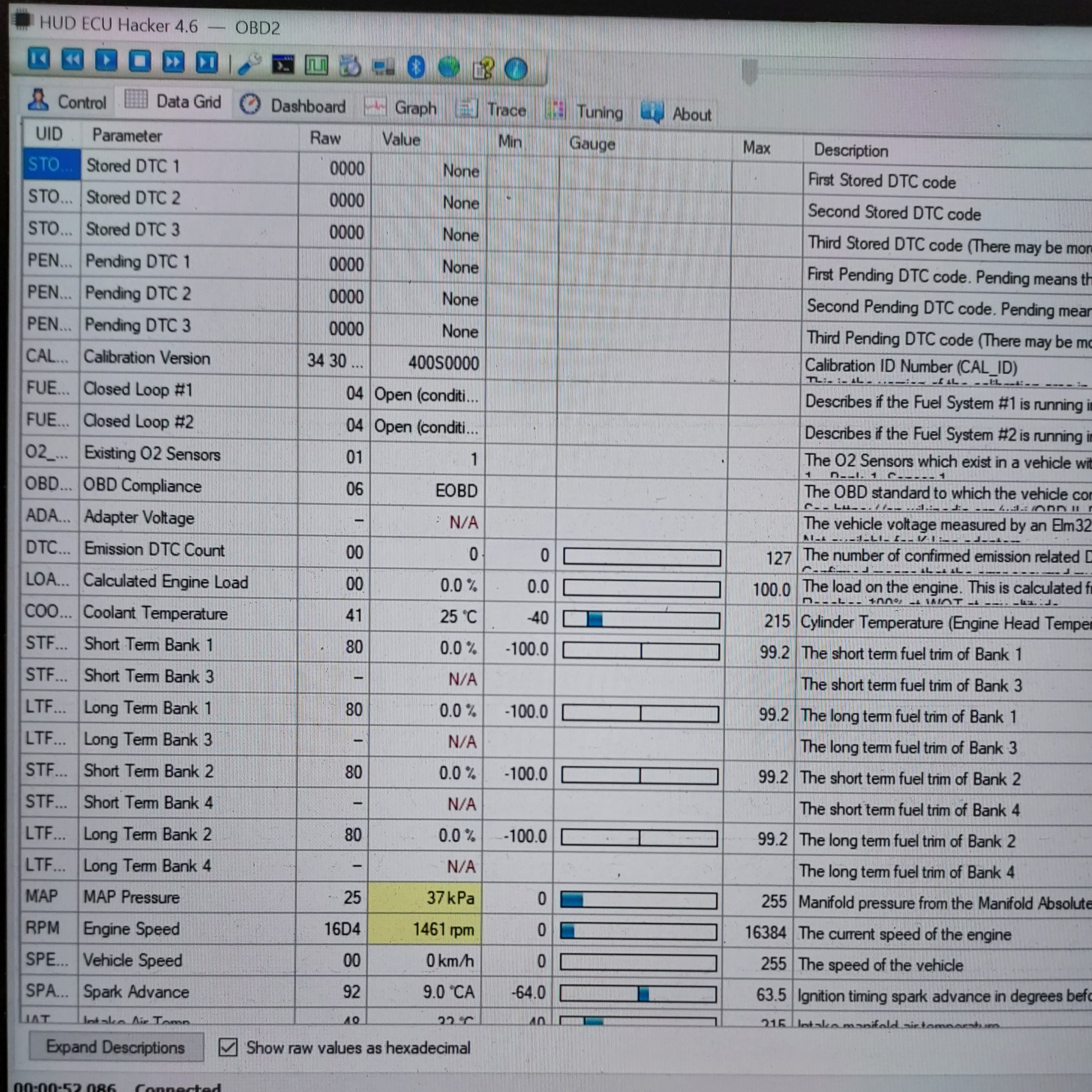
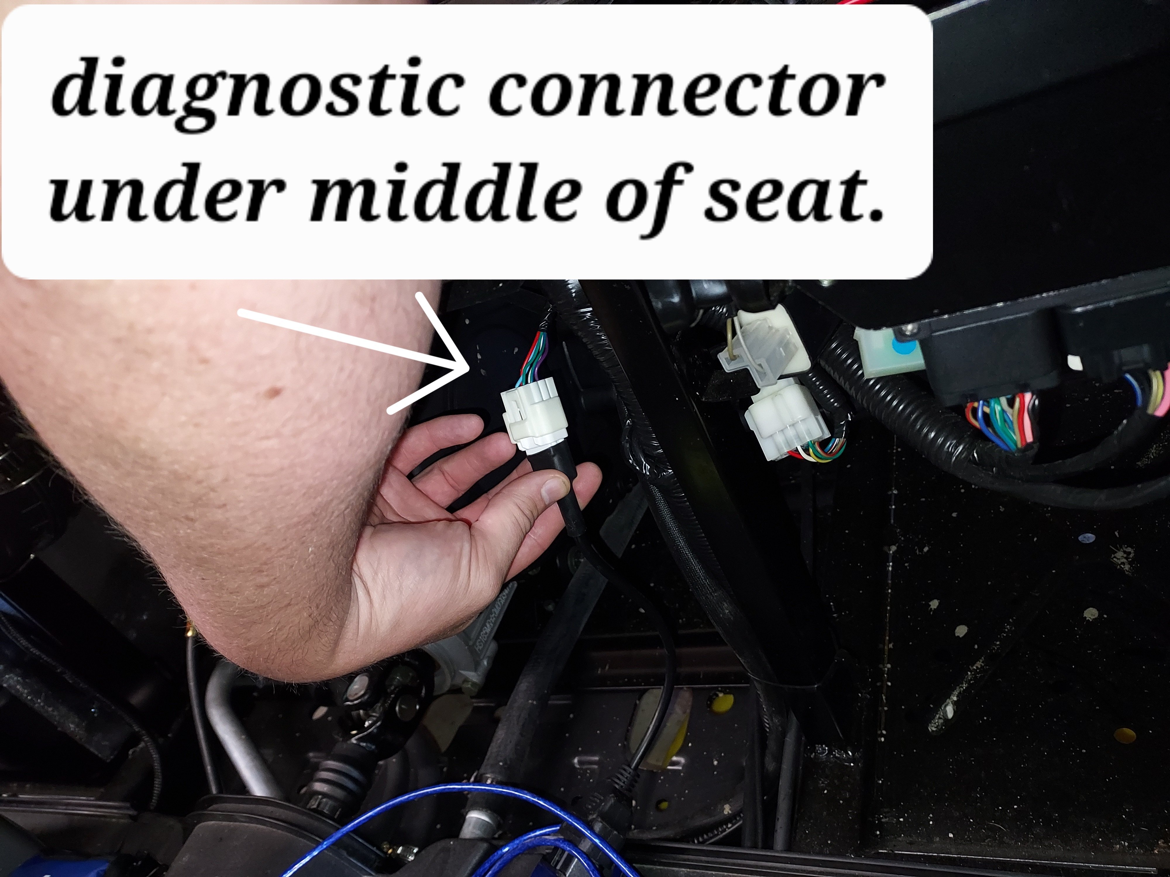
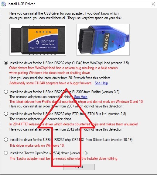
In order to connect with the ECU we need two cables. The first is a USB ODBII cable. HUD ECU Hacker’s documentation has a lot of different confusing options, but here’s what I went with and managed to get working, the cable is called “VAG KKL” it is a USB to ODB2 cable. It is available from a variety of sources for $10-15. The second thing we need is a “6 pin delphi to ODB2” adapter cable. It is also available for a similar price. In my case I ordered both from ebay, but there are other sources. Once we have our cable in hand we need to find the plug it in on your machine. My personal rig is a Coleman UT400, but the wire location should be similar for all Hisuns. My cable was located under the middle of the seat area. Just inboard of the battery, where the main wire harness split loom runs. The cable is a 6 pin (3x2) with a dust cap. Remove the dust cap and plug in the 6-pin end of the Delphi adapter cable. Note: When I was done, I left the 6-pin adapter connected, and zip tied it so it now runs to in front of the battery for easier access in the future. Next download and install HUD ECU HACKER DOWNLOAD Open HUD ECU Hacker on your PC It should prompt you to choose a driver to install. This particular cable uses the “CH340” driver (First choice on the menu) click to install, once installed hit the X in the corner to go back to the main page Once the driver is installed plug in the USB Cable, and plug the ODB2 end into the 6 pin adapter. The red led on the adapter should light up indicating it has power. Drop down and pick a com port on the main screen, it should show the VAG KKL adapter as a com port. Click connect on the main menu. It will pop up a bunch of fast scrolling text indicating it is connecting. Once connected you can click through the various tabs to see different data sets. The main menu also has the option to show fault codes, clear fault codes, reset the EPROM back to factory. The other function that may be helpful is recording a log file. You can record a log while operating the unit, and come back later and replay it to try to better diagnose what is happening. Within the various pages you will see the reading from each sensor. Sometimes a sensor reading will be off enough to cause running issues, but not enough for the ECU to realize its an issue. For example if the engine thinks it’s really warm, but its actually cold, it may not inject enough fuel to start. There are also more advanced functions, like adjusting fuel mapping, but that is beyond the scope of this tutorial. Full HUD ECU Hacker Documentation (Very technical reading) If you find this helpful give me a comment below or a thumbs up.
2 points
-
The needle adapter shown in the first post makes it so you don't need to be straight perpendicular like with a traditional grease gun coupler, You need to make sure you're buying the blunt type like that, there are also sharp needles meant for piercing rubber in ball joints, etc. With the blunt needle adapter you basically shove it into the check ball. It does make a bit more of a mess than a normal coupler, but it does fit. The driveshaft zerks are certainly have limited clearance. The other option is a small grease gun that just fits on top of the zerk without coupling. You can see one pictured in the "rear driveshaft" pic Something like this1 point
-

8 downloads
Compiled document with parts diagrams for Hisun HS400/Coleman UT400 for help in repairs where the service manual diagrams are poor or non existent.1 point -
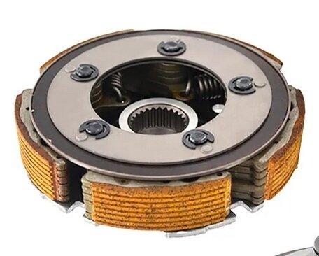
That's correct on the MA oil. Some of the info in that post is wrong. There are two things moving the power from the engine to the drivetrain: first there's a wet centrifugal clutch, from that drives the primary cvt pulley, which has a belt to the secondary. The friction material on the clutch is prone to slipping with use of additives "energy Conserving II" API rated oils, which are used in most car oils. Cars use a dry transmission, most motorcycles use a wet clutch where the clutch plates are bathed in oil. The MA rated oils don't have that additive which causes wet clutch slip issues. See attached picture of the friction disc of the wet clutch. Yellow stuff is the friction material. Once it starts slipping you get rapid wear, and also a lot of crud in your oil. Generally speaking conventional vs synthetic, synthetic oils have more uniform molecules and hence lubricate better and resist more wear and tear before going out of spec. They also typically have better additive packages, because the manufacturer expects them to be used for more mileage. Conv vs synth it makes little difference, and I would lean towards changing oil early on these machines being a large single cylinder ("thumper") they get more wear and tear than a normal car engine, and also I've read a fair number of timing chain stretching issues, which is typically an issue with accelerated wear of the pins holding the chain.
1 point
-
Hello, my name is Steve and just signing up. Bought my first UTV yesterday. It is a Massimo T-Boss 550.1 point
-
0 downloads
This is the Service manual, Parts manual, Owners manual, plus much more for my 2018 HS-550 RK UTV Side-by-Side.1 point -
You just need the VAG-KKL and the 6 pin adapter. Those I can confirm work, other ODB-II solutions may or may not work I have not tried them.1 point
-
Hi and welcome!!1 point
-
maybe he's the hunchback1 point
-
I just went through this with my axis 700 and ended up purchasing a Hunterworks cvt upgrade. I also use mine in the mountains of NC and even the 700 isn't geared for the mountains. No chip is going to makeup for this as they are just under powered for this purpose. The CVT clutch upgrade changes the gearing I would say significantly lowering the gearing for climbing hills. It will also drop your top end as well. If you go with a Hunterworks upgrade clutch you'll need a new belt as well. If you are running this in the mountains you need to keep your UTV in lower gear. If you run it in high hear you'll destroy your clutch quickly.1 point
-
Pink Floyd quote/reference. i am looking for a starter for my 2004 800 Renegade and apparently the place I dealt with before is no longer in business. Any help? Thanks in advance, Kenny
1 point
-
download my manual i uploaded here, will tell you everything you need to know and then some1 point
-
Update. Got the engine out, & removed the piston. Cylinder walls look fairly decent; no scoring I can see or feel. The 2nd ring on the old piston snapped in half as I was taking it off the piston, & they were very worn. I think that's the issue. I'll finish putting it back together tomorrow, then perform the leak down while it's on the bench. With any luck, this will fix it so it'll last another year or two. Next time, I'll just get a remanufactured engine; there's a place here in St. Louis that sells the complete engine for $950. Joey1 point
-
Hi there…one of the few disappointments with my new side by side is the low beam lights. They seem to be little more than driving lights. Is this a common complaint amongst owners? Rufus1 point
-
They probably would but I doubt you would be happy with them these are for cars not off road vehicles have you tried tractor supply or rural king or other stores of this type they usually have tires for these things1 point
-
1 point
-
Thanks for the info but shipping cost from Klung is a deal breaker.1 point
-
All kinds of Massimo new parts on ebay.1 point
-
No - it will not stay running long enough for you to do that.1 point
-
Clean the sheaves with soap and water. Then lightly scuff the sides with a brillo pad. Watch a few YouTube videos on replacing the cvt belt. Doesn't have to be same model or same machine. You are just wanting a general look at how to clean up the sheaves. Replaced the clutch 2 times on a cfmoto 600 uforce. Once just ofter I purchased the used machine. Then 8 months later after a catastrophic cvt belt failure flipped me and the wife on its side do8ng about 30mph down the highway. The belt came apart in pieces and chunks and wrapped around the sheaves. Locking the transmission/rear wheels. Then we went sliding down the blacktop. I turned the steering wheel to ease off the highway onto a grass area. Then we flipped on the driver side. Just some bruises and a few scratches. Nothing serious. After getting machine back on its wheels was able to put in neutral and push around. Then called brother-in-law to bring a trailer and load. Repaired the machine and sold at wife's request. Then got a Axis 500. Same cvt belt setup. But in her mind it hadn't tried to kill us. Lol Look at a diy tool for the secondary sheave for a cfmoto. There's a lot of guys that a tool for adjusting the clocking to remove the HD spring. I'm not familiar with your setup. But most are similar. There is a lot of force under that spring. Becareful that spring can seriously hurt or kill you. Also when I got the new Axis I put on a 5-point harness simply because the cfmoto flipped us and the lap belt wasn't enough to keep the wife from getting hurt.1 point
-
I think its interesting that this wire has a 30 amp fuse in it but the other one has a 50 amp fuse. Seems like a mismatch but perhaps different purposes.1 point
-
I don't think that is a valid error code. You can look on this website to verify HUD ECU Hacker (netcult.ch) I have this software along with the real Tetris adaptor and I can connect to the dephi ECU, read and reset error codes. I tried the cheap route as far as adaptors go but ended up buying the real thing. Here's the link to the delphi ECU manual. Microsoft Word - Delphi_CTC_Small_Engine_EMS_Service_Manual_Rev1_Eng.doc (netcult.ch) At the end of the manual are all the error codes and there isn't a 1111 listed.1 point
-
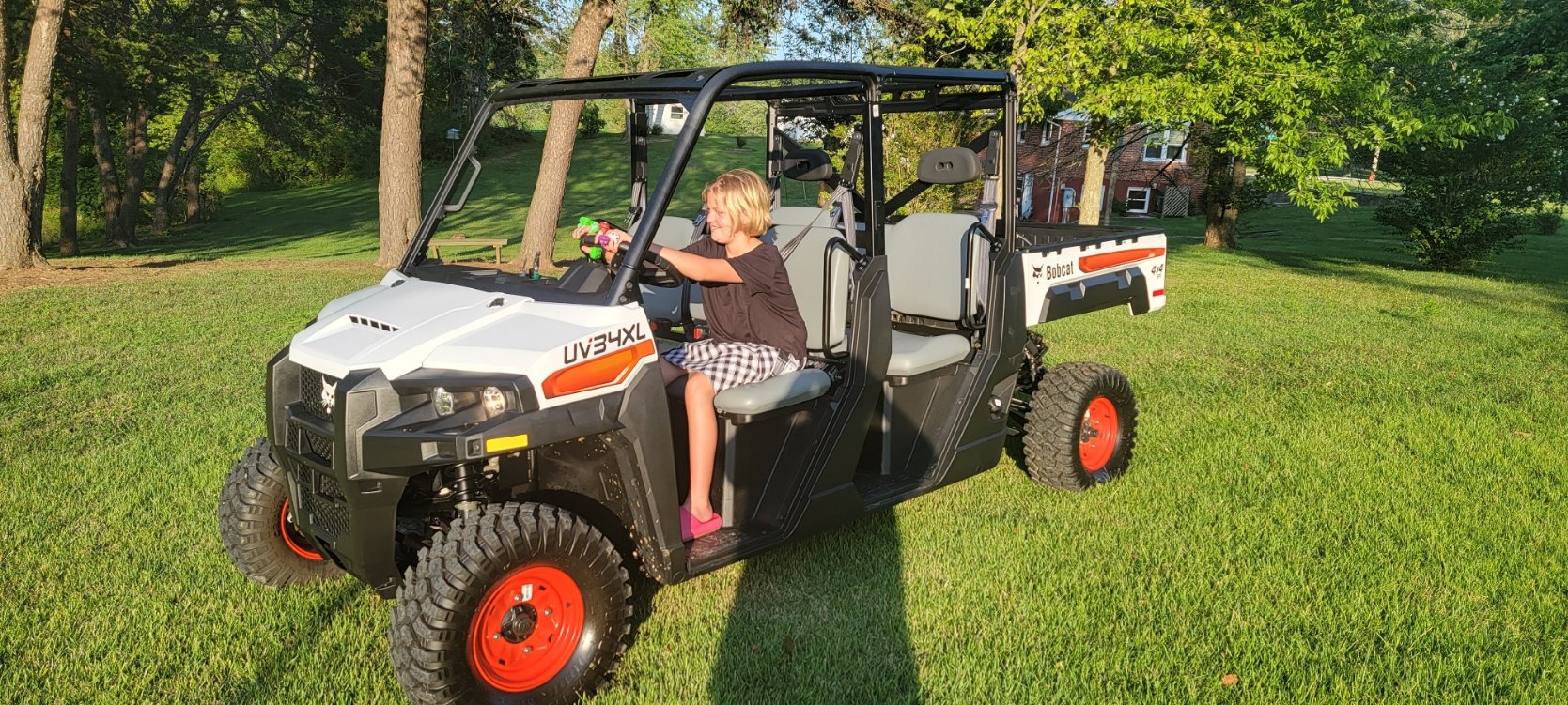
Thanks for stopping by. I live out in the country and wanted to get a good Side By Side to get around my land and the local township I live in. I picked up a '23 bobcat UV34XL (Gas), and I hope I don't bug anyone with all the Questions that I will/may have.. I look forward to reading and having conversations with everyone.
1 point
-
You're robbing Peter to pay Paul with the adjustments. You CANNOT adjust more throw into the cable. All you can do is give more F, or more R. You cannot get both with a cable adjustment. Someone actually cut the slot for the shift lever longer and then modified the detents and that seemed to help him, but the downright simplest solution is to remove the lever assembly and have it lengthen 3/4". And yes, every time it jumps out of gear, the very corners of the gear dogs are rounding off just a bit at a time. Before too long, the gears will be worn enough that they will need to be replaced. A fix sooner than later, is the key here. Good luck, Dan1 point
-
Buy new and buy quality. Otherwise you will have to spend your time sharpening your mechanic skills. Good luck.1 point
-
I agree with you, Joe. If they made a filter that could remove all the dirt and other contaminants, we would have much greater oil change frequencies.1 point
-
Well, it wasn’t either of those, after tracing wires, cleaning every connector and adding dielectric grease, no bad wires and fuse was the first thing I checked/changed. It was the relay, $45 on eBay and it’s now running again, with a much quieter fuel pump to boot!1 point
-
Same problem, did you find a solution as to why it only starts after the injector is removed?1 point
-
I currently have a 2011 Polaris 400 H.O. that has fewer than 300 hrs on it. My buddy bought it new and I bought it with around 100 hrs. I use it around the farm and to get between two properties that are about a mile apart. I am tired of dealing with the choke when its cold or even cool out. It starts fine and runs ok if your driving but until it gets completely warmed up if you pull up to a gate and get off to open it will die. And because of the choke my wife has a hard time with it. Before I got the 400 I had a 2013 polaris 500 midsize that was fuel injected but aways ran rich and foul plugs. I had it at two different dealers and neither one could fix it. So I sold it and bought the 400. My father in law has a 2015 Polaris 570 midsize which is fuel injected and it is hard to start and cranks more than it should. Needless to say I am done with Polaris and ready to sell mine and move on to something better. I have been looking at the Honda Pioneer 700 and the Kawasaki Mule Pro MX. I was disappointed to learn the Kawasaki Mule Pro MX engine is built by Hysun and not Kawasaki, but that maybe a non issue. Maybe I'm missing another good option that I haven't considered. The main thing is getting something that is bullet proof reliable. Any feedback would be greatly appreciated. Thanks in advance1 point
-
Roger - Inability to properly shift into both Forward and Reverse is a common problem with this unit. You get one or the other along with gear grinding. It is what appears to be a design flaw with the Coleman UTV400. Another thread exists on this board describing it. Two fixes so far: DIY an extension to the shift handle to increase the throw distance or wait for Coleman to supply a fix-it-kit to your Warranty Service Shop and get it done there. In my case? Still waiting. However, we've been able to mostly make things work. On our Coleman UTV400, Forward works fine with an occasional gear grind starting out. Reverse was and is a better-pay-attention issue. We found that rather than slamming the gear shift all the way to the bottom of its throw, stop approx. halfways between Neutral and full bottom. With a hand on the shifter and fluttering the gas pedal, we've found that usually we can feel the shifter (and transmission) settle into Reverse. Until a real fix happens, we don't put ourselves in any MustBackOut situations. Regards, Ted in OK1 point
-
Obviously Joe you're on an anti-HISUN mission. Just speaking for myself, I'm tired of your constant bad mouthing my machine!! You've made your point, get a life!1 point
-
Got a outer rebuild kit. Everything worked great.1 point
-
That is just normal operation and the same with cars and trucks! But the issue is with these the firewalls are not insulated!!! so we feel it1 point
-
Your stator is a 3 phase "Y" output. The winding "LEGS" are the 3 white wires......call/label them A B C. Look at a parts list to see the stator is a laminated steel ring with a multiple of 3 poles---like 12 or 15. The windings are connected BUT NOT TIED TO GROUND at the starts----thus the schematic Y look. Each leg is wound in series on every 3rd pole and act like stacking a string of batteries in a 5 cell flashlight....except the poles produce AC. The AC output is measured from white to white, white to white, white to white.........A-B, B-C, and C-A. Idle voltage is around 20 VAC leg to leg (3 times). Higher RPM will produce on some systems around 80 VAC.....CAREFULL HERE. The resistance check (here again leg to leg) is thru 2 sets of pole coils.....IN one of the whites----to the center tie point----OUT to the 2 other white wires. Measure A-B, B-C, C-A...... .2 to .3 ohms. Also check for any path to GND....high M ohm scale should be infinite as in open circuit. A 120V/40W light bulb will glow when connected A-B, etc. Some systems will blow the bulb if motor Rs too high Your problem with the melted connector plug was corrosion. The connection resistance will heat up the terminals and with enough heat, melt the nylon connector body......this goes on for a while THEN it goes BAD when the terminals touch.....shorting out the STATOR windings. If opened up, you will find the varnish burned off 2/3 of the 2 legs effected. The coils short down and the resistance check will be sub .1 ohm. Output voltage test will NOT be equal leg to leg also. As an added bonus, the stator will cook off with additional engine run time. I found that the voltage REG will still be good.....burned terminals and all.....most of the time......but die later. The RED wire goes to the + battery terminal. Black goes to GND....- BATTERY POST. Test with a test light to ensure a good connection as in probe to REGULATOR RED wire and clamp to GND AND probe to REGULATOR BLACK wire AND CLAMP TO BATTERY + POST. Voltmeter will lie to you and say a good connection. An example would be BLK test lead to GND......lick finger and touch RED meter lead AND use another finger to touch the + battery terminal.....meter will read 10 to 12 VDC...says you have a good 12V....NOT. BONUS HINT: finding the correct connector and terminals to match the REGULATOR might be tough. FIX is to use a aftermarket RICK's regulator that has pigtails.......cut and strip both stator and regulator wires.....match R and B......the 3 ph whites don't matter...totally random mix when harness was produced and regulator has 3 identical input circuits. TEST STATOR FIRST FOR DAMAGE/FAULTS.1 point


This leaderboard is set to New York/GMT-04:00
