


cliffyk
-
Posts
350 -
Joined
-
Last visited
-
Days Won
49
Content Type
Profiles
Events
Forums
Gallery
Downloads
Community Map
Posts posted by cliffyk
-
-
If it comes down to it you could toss the connector completely and use butt or better yet, barrel (bullet) connectors that can be easily disconnected if needed--though the latter seem to have fallen out of fashion, I no longer see them in the auto parts stores...
-
Often we have to forget about the ways things were, and make 'em better. Will the connection point for the switch's harness accept plain ol' 1/4" or 3/16" male spade terminals? Can I say that or should I say "terminals of colour" (TOC)?
If so you could ditch the connector body and put new male terminals on each wire and connect them individually? It won't be as convenient, however you will be making sure ALL the terminals are crimped properly, and properly bedded in dielectric grease so the corrosion does not happen again.
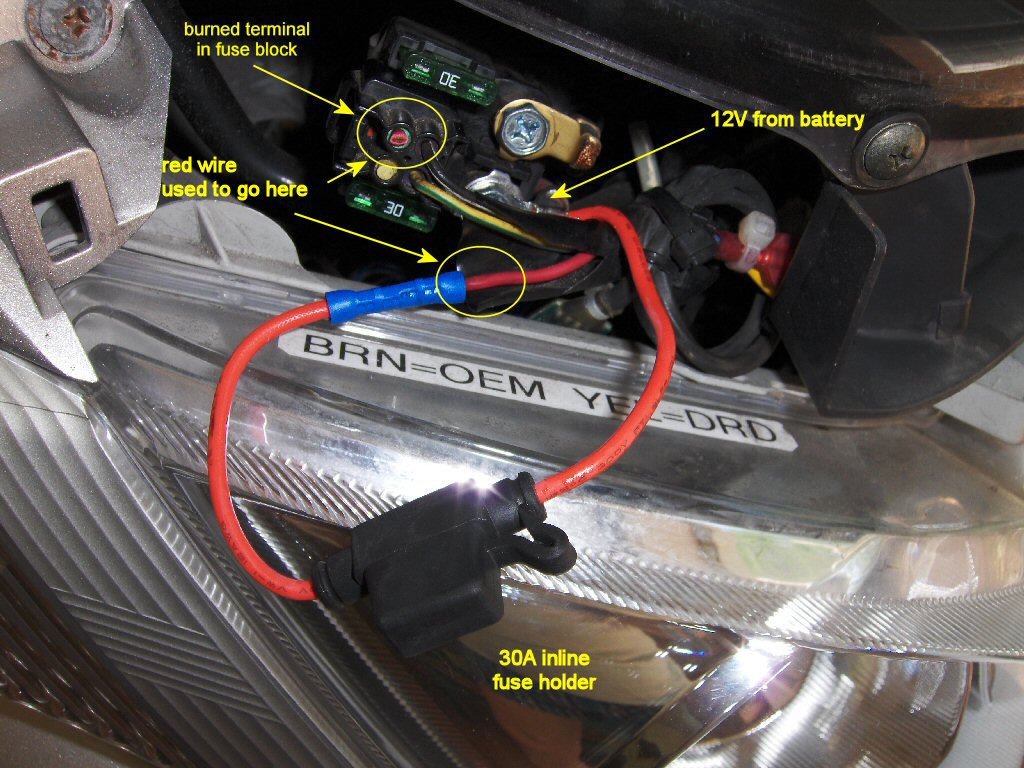
The main fuse block 30 A "accessory" section on my 2003 Suzuki Burgman 400 burned up, it was over $100 for a replacement--so I just bypassed the whole thing with an inline fuse:

Sometimes you have to think on the other side of the box...
-
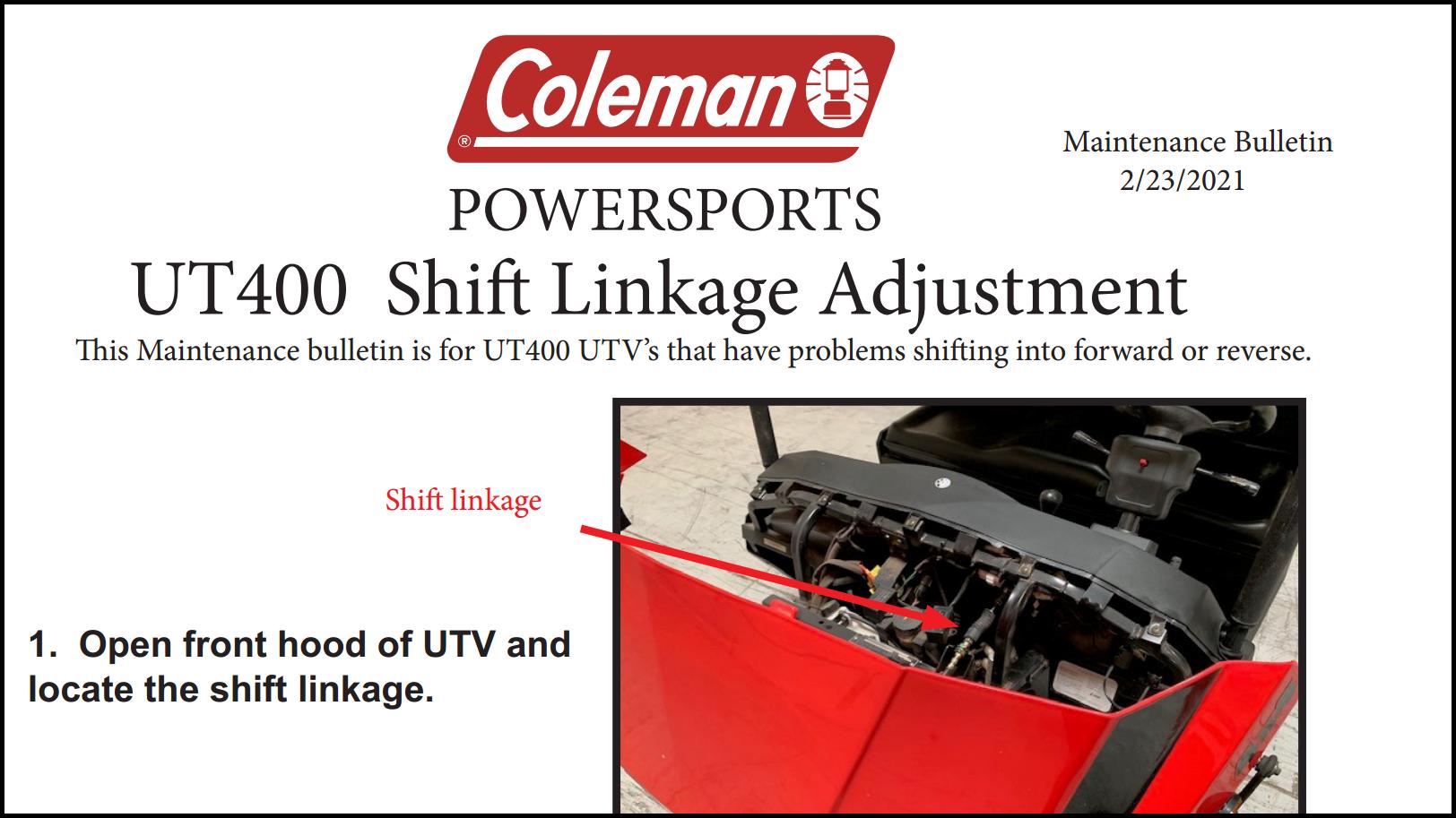
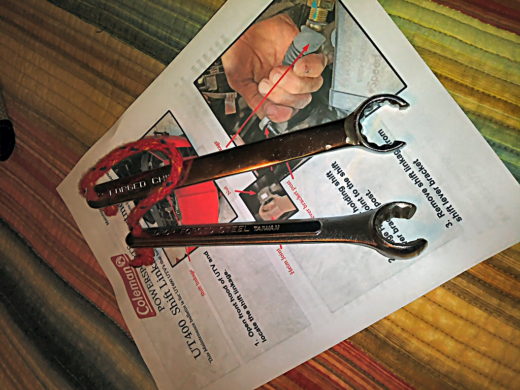
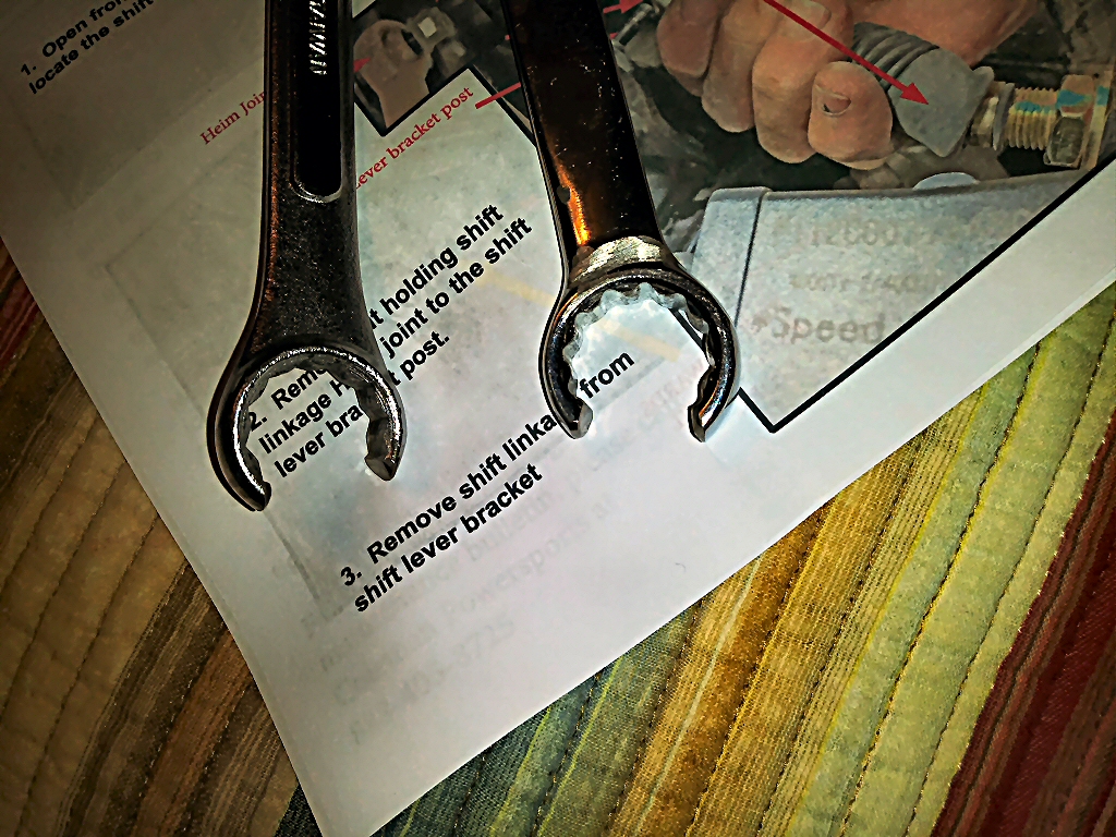
Outfitter-UT400-ShiftCable Adjustment
I got this from Coleman, detailed instruction re: shift cable adjustment...
I forgot to mention you will need two 22 mm wrenches for the cable lock nuts. I hacked up a couple of cheap "quality tools for less" combination wrenches using a cut-off wheel in an angle grinder:
Kind of like "flare nut wrenches", good for light duty like this.
-
Submitter
-
Submitted03/19/2021
-
Category
-
 2
2
-
-
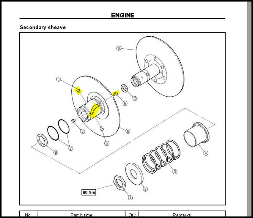
Just had a thought, reverse is generally a lower"gear" (a numerically higher ratio) than any forward gear--that means for any given vehicle load less torque being transmitted through the CVT. That lower torque requirement could show itself if a jammed up movable pulley face in the torque multiplier is also present,
The spiral slots in the outer (movable) pulley hub are the Torque multiplier cams--the pins (p/n 5) are the cam followers)
The torque spring (p/n 3) forces the pulley faces together, working against transmitted torque to keep the driven pulley effective diameter large and the variator (drive pulley) working diameter smaller (I.e. a "lower gear)--this happens while the variator centrifugal weights are also trying to make the variator pulley effective diameter larger. This battle between the two is part of what determines the overall CVT ratio.
However when torque needed to accelerate the vehicle reaches a certain level the belt slips on the inner (fixed) driven pulley face but not on the movable face causing the outer pulley half to try rotate--if it can rotate the torque multiplier cam and its followers work with the spring to force the driven pulley faces further together to further increase its effective diameter (if not already closed completely) and thereby forcing the variator face apart decreasing its effective diameter--temporarily forcing a lower yet over all ratio until yet another equilibrium is struck. when vehicle torque demand falls off. This is why the assembly is called the "torque multiplier".
If the outer multiplier pulley was jammed on its shaft unable to rotate and effect pitch diameter , a lower torque demand (as in reverse gear) could cause the belt to effectively loosen, slip in both sheaves , and squeal.
110% speculation, but its been 8-9 months, what else do we have? And I would bet "dollars-to-donuts" it's a CVT issue.
Not sure I explained this fully or sufficiently clearly, if anyone has questions or comments let 'em fly...
-
 1
1
-
-
My first thought when I read "belt squeals": is that the rubber band in the CVT is severely glazed-that's the only thing in there that can "squeal"--if the belts looks good I'd pull apart the variator (drive pulley--often and quite incorrectly called the "primary clutch")) and torque multiplier (driven pulley--often an d quite incorrectly called the "secondary clutch") and make sure all components in same meet their specs (primarily the roller weights in the variator; and spring, torque cam and cam followers in the multiplier.
Though I really don't understand why such problems would be unique to reverse gear.
-
1
-
-
1 hour ago, Travis said:
are you sure the throttle cable isn't broke? over time they do need to be adjusted to compensate for wear.
^^^ this, make certain that "flooring" the accelerator pedal causes the same linkage motion at the carburettor, as does manipulating the linkage directly at the carburettor. If not then suspect the throttle cable and/or some deformation or blockage in the pedal mechanism...
-
I haven't seen mention of the oxygen sensor (in the exhaust pipe) in this discussion. A dead or dying O₂ sensor will generate a low, or no, output voltage; this makes the ECU think the engine is running lean, it compensates by adding fuel, I.e. making the AFR rich. This can happen without triggering an error code.
For more (than you probably want to know) about O₂ sensors--including how to test them with a multi-meter and a propane torch--click here.
-
That looks like a good candidate for some aerosol contact cleaner, Q-tips, toothpicks and conpressed air.
However I have on occasion poked around a bit inside the body with a dental probe and been able to find something that would release the terminals in connectors like that--typically they pull out from what is the bottom in your photo (the "business end")--there are specialty tools for disassembling these things. Search for "Tool Disassemble electrical connectors" on Amazon. I had a set years ago and it worked great on the connectors it fit, but as is common with real world perversity, most of the connectors I wanted to take apart were ones none of the "keys" fit.
Sometimes there is a plastic locking tab holding the terminals into the body.
-
1
-
-
sometimes there's a plastic tab on the body, or a metal tab on the terrminal that lock things in place--however more and more in the modern world the terminals are moulded into the plastic body and not removable. I fall back to Q-tips ,toothpicks, a suitable solvent, and elbow grease on those.
-
1
-
-
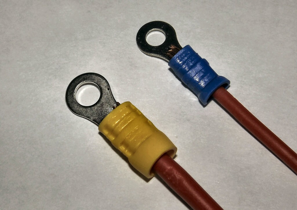
The white-brown contacts provide (via the brown wire) +12V power to the lights, horn, brake lights, and the coil of the starter relay. 2.3 Ω is quite high , did thet measurement "include" the corroded connector?
A modest 2 A load through that 2.3 Ω resistance would produce a 4.6 V voltage drop--leaving just 8.0 V (of a fully charged battery's 12.6 V) to "do the job".
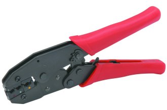
Obviously the corroded terminal needs to be replaced. In doing so make sure the wire is clean and shiny, and use some dielectric grease (SuperLube's PTFE grease is very good for this)--$6. at Home Depot--to "pot" then connection. Make sure you use a good crimping tool also, like this "full compression" tool from HF:
This tool will create very reliable connections unlike those tools that just "squash" the terminal ferrule.
.
I suspect your recent manipulations of the wiring disturbed some poor connections and made them conduct. This is not uncommon, in emergency situations it can be, and has been for many, a viable action to get going again,,,
-
1
-
-
19 hours ago, kenfain said:
Sometimes it's displayed as a number on the clock. It might not blink, but just display the number. I don't know how many sensors there are on yours. But with what's going on with yours, there should certainly be a code. Have you looked at switching the upstream, and downstream exhaust sensors?
^^^this^^^ The codes display just like the clock display, but the colon (":") is dimmed out--they are easy to miss except that they do not change each minute--The EPS (Engine Protection System) warning light should be on if any error codes have been logged.
-
10 hours ago, ccam111 said:
I am having the same issue on a Massimo 2016 msu800. Did you figure out the issue?
Try loosening the fuel cap for 10-15 seconds then re-try starting it--might not work but it's worth a try...
-
4 hours ago, Travis said:
Hope so. i wish there was a test for the switch , like you can test the circuit relay, but the keyswitch is all sealed up, and no testing procedures are listed in the manual.
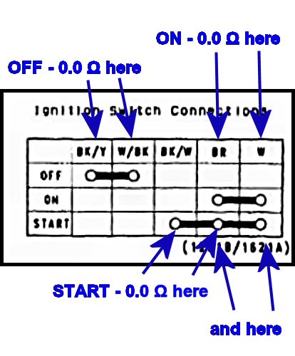
Your wiring diagram provides the ignition switch contact "rules" for its various positions--you can test it by checking continuity with an Ohmmeter as shown below:
Connect the Ohmmeter to the wires/terminals as shown and check the resistance with the key in the indicated position--it should be 0.0 Ω or no more than 0.2 Ω.. This procedure tests the switch at low voltage and current as used by the ohmmeter, however it will be a valid indicator of the switch's functioning properly...
Note: this test is performed with the switch NOT plugged into to the vehicle.
In "OFF" there should be 0.0 Ω between the black/yellow and white/black wires
In "ON" there should be 0.0 Ω between the brown and white wires
In "START" there should be 0.0 Ω between the black/white and brown, black/white and white, and brown and white.
The "OFF" position connection of the black/yellow and white/black wires grounds the ECU when the switch is off--a safety precaution against static discharge no doubt.
-cliff-
-
2
-
-
Joe, I likely overreacted--it is a topic I am a bit peevish about--on Labor Day of 2019 the family had a celebration of my accomplishment when my drunken 27-year-old step-grandson¹ stood in the centre of it all, and declared for all to hear; that he "didn't think it was that big a deal"
His mother ad father very nearly died right there on the spot.
My wife says I bring it up too often--she's probably right (why are they so damned right so often?)--but for me it represents the likely "end posts" of nearly 50 years of work and aspiration--it is an accomplishment I am quite, and no doubt overly; proud of...
----------------------------------------------------------------------------
¹ - Whose life accomplishment after dropping out of UCF is being a part-time barmaid at Starbucks in Orlando.
-
I have never before in my life had the content and purpose of a post so poorly understood--must be getting old.
-
That's pretty much what I thought I said.. My specific point was that we (and I am as guilty as anyone) have been using the term "solenoid" to refer to both the electro-mechanical device on the starter motor that both causes the starter motor drive pinion to engage AND closes the heavy duty contacts (typically a copper disk and the terminal bolts heads) to switch power to the motor. This has caused confusion in the discussion.
-cliff- (MSME MIT '71)
PhD ME MIT 2019--how I spent the first three years of my retirement
-
Cool... Pretty much as I expected it to look. That neutral switch could be a culprit too--a simple test would be to jump or connect that light green wire at the neutral switch to ground. That will bypass the switch ruling it out as a bad guy (or proving it to be the bad guy)...
-
1
-
-
I think we need to establish a taxonomy for this discussion--specifically re: the often misused term "solenoid".
Classically a solenoid is an electromagnetic device in which current flowing through a coil attracts an iron armature to create motion--not specifically an electrical switching relay, though all such devices are technically solenoids. Solenoids do mechanical work often without switching contacts. Remote door and trunk locks are activated by solenoids typically with no switching function.
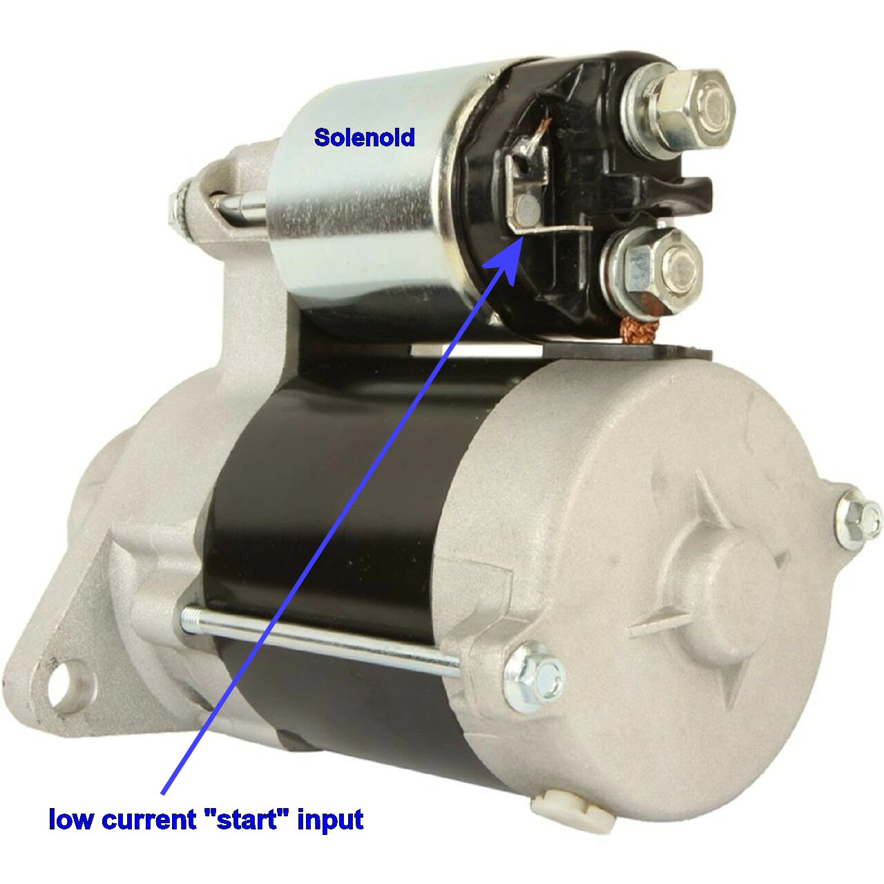
Umfortunately in automotive terminology it has come to be the term for the high current relay that switches power to an engine's electrical starting motor--with no other function. However in the instance of the 2001 Mule which has a somewhat "old school" (for a motorcycle type engine) pre-engagement drive starter the solenoid has two functions: 1) to mechanically position the starter's pinion gear into mesh with the engine's flywheel; and 2) to close electrical contacts to supply power to the starter's armature. Here's what that puppy looks like:
The big round thingy on top of the starter motor is this starter's solenoid. Battery power is permanently (I.e. not switched) supplied directly to the topmost large terminal--the bottom-most terminal is connected (through brushes) to the armature. The small 1/4" male spade connector is where power is applied to activate the solenoid so that it will push the pinion gear into engagement with the flywheel, and close the main electrical contacts connectin the top and bottom terminals to power the starter motor.
Typically is this configuration there is another somewhat high capacity relay that switches power to the starter's solenoid. these other relays are also often called "starter solenoids" which can and often does lead to confusion in trouble-shooting discussions. I do not have a 2001 Mule schematic at hand, however I suspect it might included such a high capacity relay for supplying +12 V to the starter's solenoid. In our discussions we need to make sure we differentiate the two--perhaps "starter relay" and "starter solenoid".
Further confusion comes about because with the contemporary constant mesh starters there is typically a remote mounted high current relay often also called (sometimes even in factory parts lists) the starter solenoid where technically it is just a high current relay.
Starter mounted solenoids can of course bed replaced ad hoc, but typically they are an included component of a new stater.
-
1
-
-
AFAIK the "hard coat" is part of a manufacturing process, not some "after-the-fact' application--could be wrong about this though...
-
1
-
-
Cool... Please let us know how it goes...
-
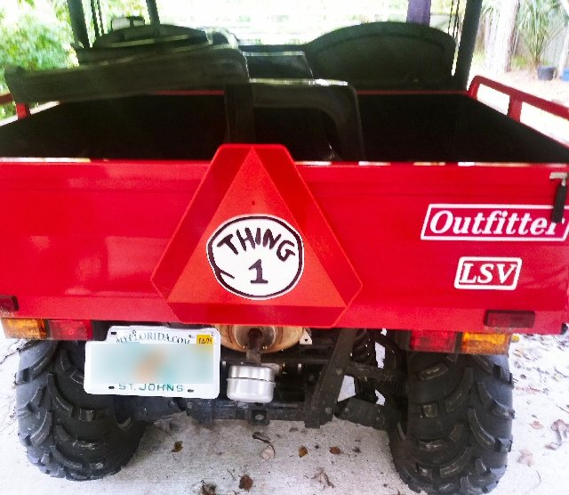
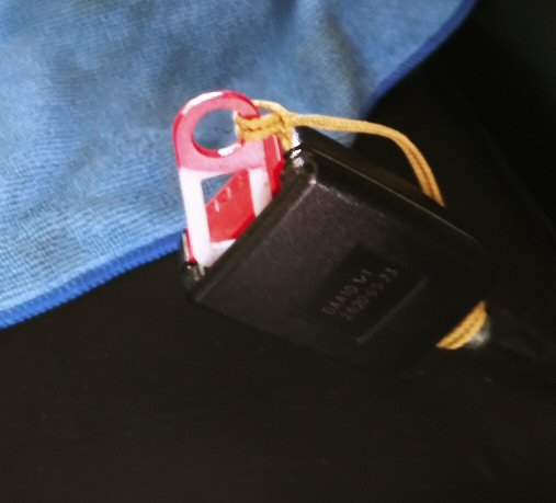
Big Brother is always watching out for us!
Here's what it actually looks like, "unplugged"--quite unobtrusive when "plugged in", just the red tab shows :
I am doing well, thank you for asking... The good part is I have an official document stating I cannot wear a seat belt.
-
1
-
-
My understanding from scouring parts lists for my 400 is that the base engines (valve timing, lift, etc.) on the carb vs. EFI engines is the same--it's only the fuel system and controls that differ. I would expect the 700 to be the same. I.E. your carburettor, fuel tank, etc. should work on an "EFI" engine...
-
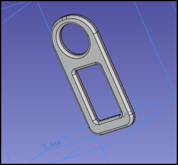
It will not go over 10 mph unless the driver's seat belt is buckled. Or the "safety" interlock defeated in some manner. Removing the limiter module does not work. You can buckle it behind your back but that's a bit uncomfortable. You'd think they would mention this in the manual--wouldn't you?
I 3D printed some tabs that mimic the seat belt male connector.to trick the foolish thing
It is 45 mm x 20 mm x 3 mm, just a clone of the seat belt connector. I have made these for my other vehicle's as well. I had open heart surgery a couple years ago and cannot wear a shoulder belt.
If you send me a SASE I can mail one to you--I will send you a PM with my address.
The normal level of the coolant t reservoir is quite low in the tank--you have to peek in around the framework to see it. The black tubes are exhaust outlets for the generator and CVT air-cooling.
My gas gauge works fine, I have seen reviews on he Tractor Supply web site reporting it did not.
-cliff-
-
5288 miles in 628 hours is just 8.4 mph average--so it appears it wasn't beat up too hard. I'm right around 14.5 mph average in 37 hours on my Coleman Outfitter 400--there's a lot of flat open land here--I can hit 40 on the power lines down the road from my house.


What do you do when
in UTV General Discussion
Posted
Did it strike you as odd that not a single aide or SS agent rushed in to assist? It's almost as though they are hoping he'd break his neck, so Camela can take over (my most recent recurrent nightmare)..