


Leaderboard


Popular Content
Showing content with the highest reputation since 04/28/2023 in all areas
-
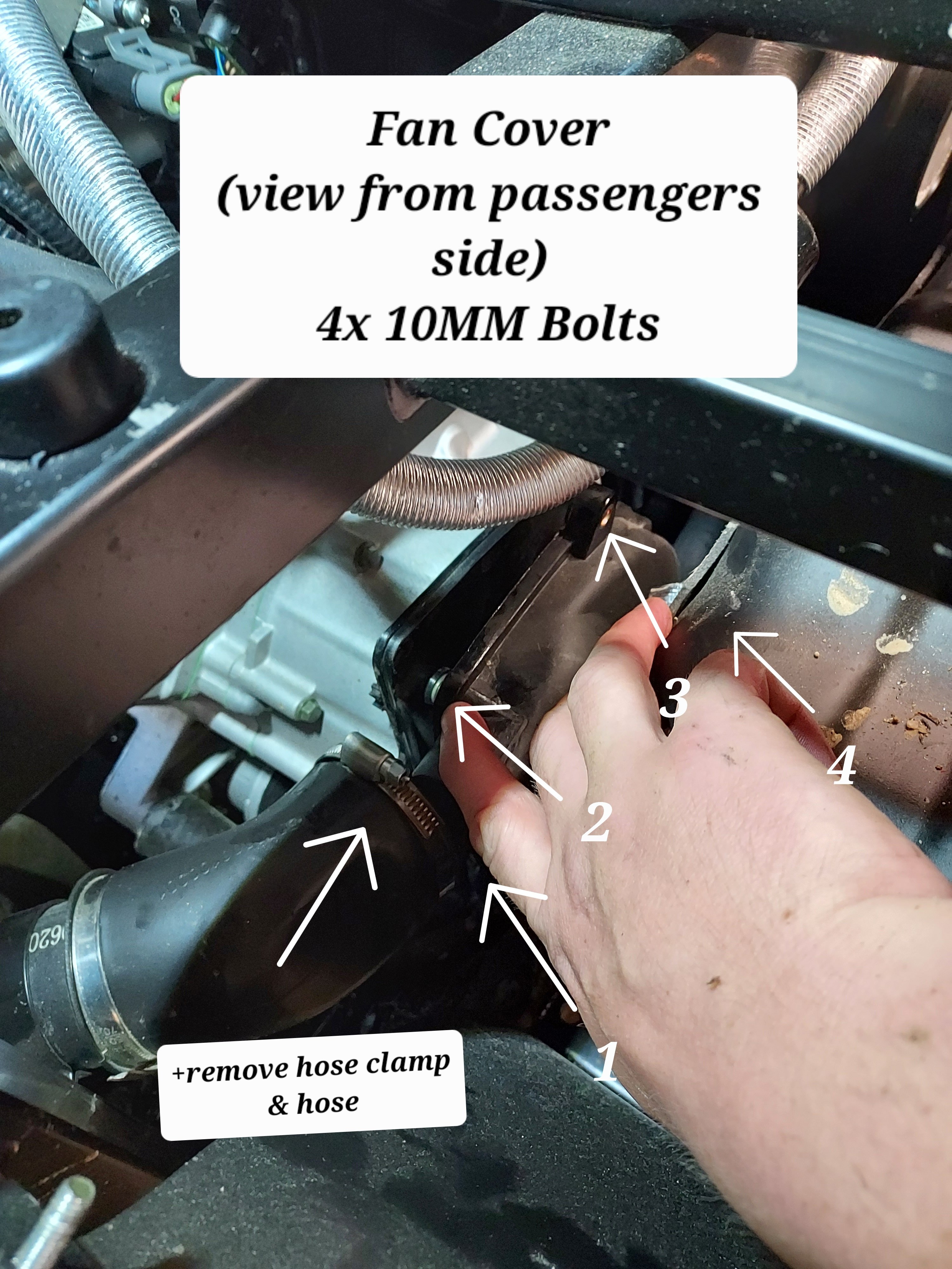
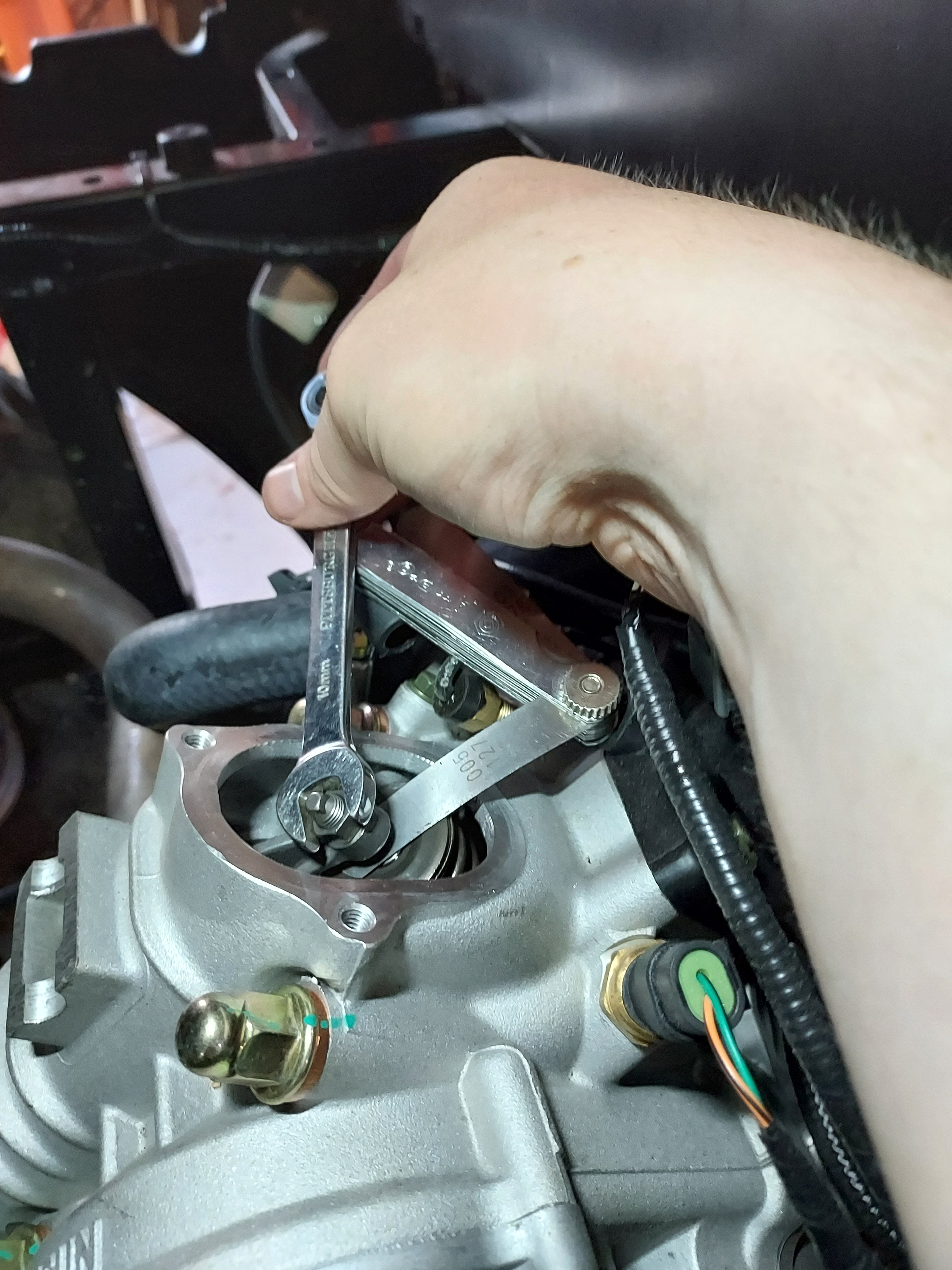
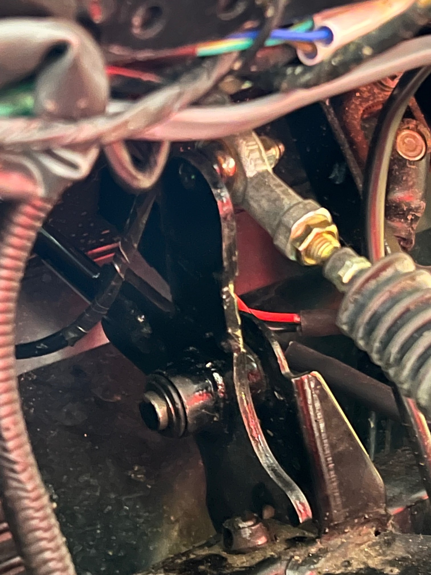
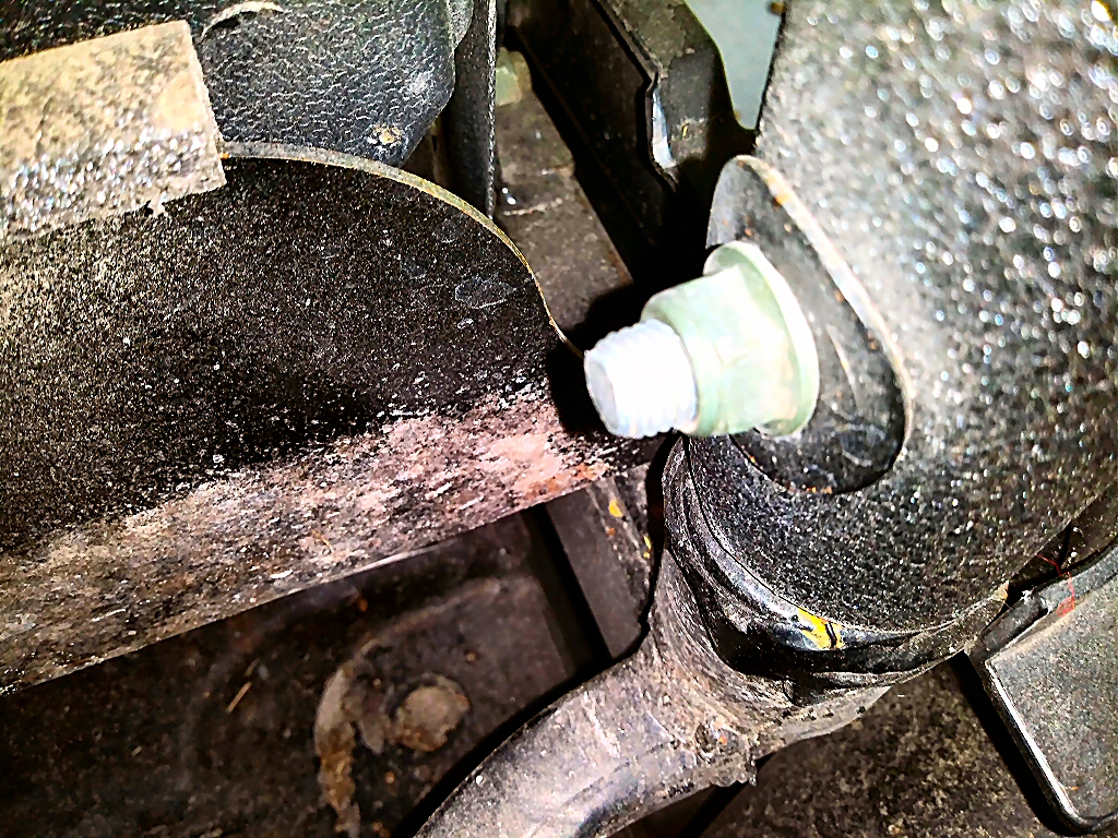
Since I've seen some questions on this I took some pictures and will provide instructions on a valve adjustment for the UT400. This should be the same for the 550's and other various Coleman/Hisun single cylinder models with the cylinder slanted aft. I have seen several people ask of it is really necessary, and read several reports of valves being out of adjustment from the factory. My valves were .004" intake, and .010" exhaust with about 5 hrs on the machine. I've seen different numbers thrown around for factory spec, but I decided to go with 0.005". This is called valve lash. What is is is a gap between the rocker arm and the valve then the camshaft isnt opening the valve. Why does it matter? If it's too large the valve doesn't open all the way, if it's too small the valve dosent close. This can cause valve damage (overheating) as well as loss of engine power (burned fuel is going out exhaust rather than pushing the piston dow). Tools required : 5MM Allen wrench, 10MM box wrench, needle nose pliers, flat feeler gauge set, rags First you need to remove the fan cover on the passenger side. There is a cooling vent hose on the back side, remove the hose clamp and slide it off. From there there are 4x 10mm bolts holding the cover. The forward ones can be accessed from under the seat. Next remove the spark plug from the drivers side. Carefully wiggle the spark plug wire off. Grip it as low as possible and give it a little twisting motion as you pull it off to help free it. Its a tight fit for a socket, but there is a sheet metal wrench in the toolkit that fits it. Unscrew the plug and set it aside. This allows you to spin the motor over freely with no compression to fight. When you reassemble this is a good opportunity to switch to an NGK iridium plug for better performance/less fouling DR8EIX) Next you need to remove the intake and exhaust valve covers. The intake us the forward one. There are 3x 5MM Allen screws to remove. The Exhaust is the rear with 2x 5MM Allen bolts. Both covers have O-Rings instead of gaskets and are reusable. When you remove the rear be careful and use your rags as there will be oil that drips out. Next up we need to spin the motor over to top dead center. Grab each rocker arm and give em a little wiggle up and down. Spin the engine over by grabbing the fan with your other hand. Spin the engine over until both rockers have some wiggle and are loose. Once both rockers are loose slide the feeler gauge in like shown above. Try different feelers as needed to determine your starting spec. You should feel some drag but still be able to move the feeler without too much force. If you need to adjust, use the 10MM wrench to slightly loosen the locknut, then with the correct feeler gauge in place, tighten the top square nut while wiggling the feeler in and out. Once you have it right you need to tighten the 10mm lock nut without moving the square head bolt. Once the lock nut is tight recheck the clearance. That's it, button everything back up and make sure you have it all reassembled before running it again. If you find this helpful give me a thumbs up or comment. If you have any questions or need more help let me know. If there's interest maybe I'll do some more of these
 4 points
 -
Hello to anyone who reads this. I am Jon and I own J&M Outdoor Power, a very small, small engine repair shop. I was approached by Coleman about 6 months ago to become one of their Warranty Centers. I recently received 3 different UT400's and a UT500 all with similar issues. These units range from 2 months to 2 years old. Customers state that the unit(s) was/were running fine, then heard a pop and a loss of power, two would no longer start. The two that would run would not achieve normal operating speed (around 20mph I would say) without redlining the RPMs. I quickly found that the Valve lash on each unit had become too large on some(both intake and exhaust) and too tight on one(just intake). After setting the gaps to .005(I found multiple different people suggesting bigger and smaller gaps, but no definitive Coleman Spec number yet) every unit starts, runs, and achieves top speed without issue. I don't know how many others have come across these issues, and I wanted to get something out on the web for others in the same predicament. Please let me know if you have had similar issues. Edit: I realize that this will not be a fix all solution for this issue, as the oil level and condition should be verified before moving to the valves. Many times improper oil conditions will cause valve lash to change. These units all have good oil and proper oil changes.3 points
-
Are you talking about an electric heater? if yes its likely too much current. There might be 10 amps of available current coming out of the rectifier that isn't already claimed by the ECU and factory lights. 10 amps @ 12V = 120 Watts, which is about what an electric heating pad runs. If you're talking about a fan for a engine coolant based heater it's probably ok. If you have accessories and the running voltage is below 13.5V you have too much stuff attached. If the battery light comes on it means the battery is actively being discharged while running. Stator based charging systems on these things and tractors etc are really meant to power the ECU and factory systems not to provide a lot of extra power for other stuff, it's not like the alternator on a car.2 points
-
happy new year!2 points
-
The main trick is tilting the front end up. Block the rear wheels and jack up the front end at least a foot. A convenient ditch works well also.....rear wheels in a shallow ditch. The head bleeder screw should be opened. With the engine NOT running, almost fill the radiator (leave some air to avoid a mess) and burp (squeeze the lower hose line before the metal tube at the engine base passenger side floor area). Watch the radiator and the the bleeder. With the radiator "higher" than the head bleeder, the air should be bled and coolant dribble out. Close the bleeder and refill radiator (your clue you displaced the air with coolant) and start the engine. Burp more while running and if you get the circulation going the hoses will warm up. More bubbles should surface at the radiator filler neck. Shut off engine. Open bleeder and release any air in the head. The puke jug needs to be filled about an inch above the full cold line. Use a shop towel as a "seal"and use an air nozzle to SLIGHTLY pressurize the puke tank removing the air from the tubing line to the radiator neck. Then the radiator starts to overflow, a third hand can install the radiator cap. Run the engine and determine the head and hoses are at the close to the same temperature (as in warming up) through out the system. IR temp gun....fairly cheap now....can get real numbers. Scan the radiator, hoses, cylinder and head.....if all close you are done. Recheck fluids when done riding. Recheck the bleeder and top off the puke jug as required.2 points
-
From the look of the picture on the post, I can think of a couple things2 points
-
Its' not a car, this is a motorcycle engine with a small stator charging system. You can't expect to run high wattage accessories like a heater or huge light bars on these things . That will overwhelm the charging system, drain your battery an stop your engine. Could damage the charging system and voltage regulator too. You only have about 10 amps extra to run any accessories including lights.2 points
-
My dealer gave me an electronic version of the service manual and I have sent it to Kingfish. I will see if it will upload here for others to use. I'm not sure if there is a more appropriate way to do this, let me know if there is.. 2015-2017 Service Manual - Sector E1.pdf2 points
-
my Hisun in my Massimo , sold by Tractor Supply, assembled in Dallas, say Made In China on every part of all of it .. Altho it now has multiple Yamaha parts mixed in. lol2 points
-
https://motorcycledoctor.com/wp-content/uploads/2021/08/Valve-Adjustment-HiSun-2.pdf This should do it.2 points
-
Yeah, I adjusted mine multiple times without any luck. I had extended the shifter rod, as mentioned on this board, as well as some videos I watched, and that resolved the shifting issue. Now, after it slips into forward or Reverse, it never slips out. PS: If you go this route, remember to readjust the cable to compensate for the extended shifter. I had to do the adjustment an couple times after extending the shifter and then the problem was resolved.2 points
-
I finally found a service manual in stock and was able to make the adjustments per the specs!2 points
-
Problem was using cheap eBay injector. Bought quality one and hot pipes went away. Running like new.2 points
-
Buddy, I've been using that phrase a whole lot lately.2 points
-
Massimo MSU500 won't shift to low I would check the shift linkage. Adjust it make it a little longer, if it is not long enough it won't shift to low2 points
-
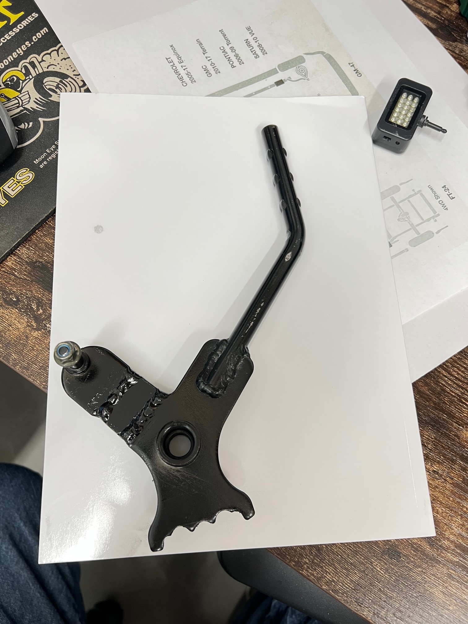
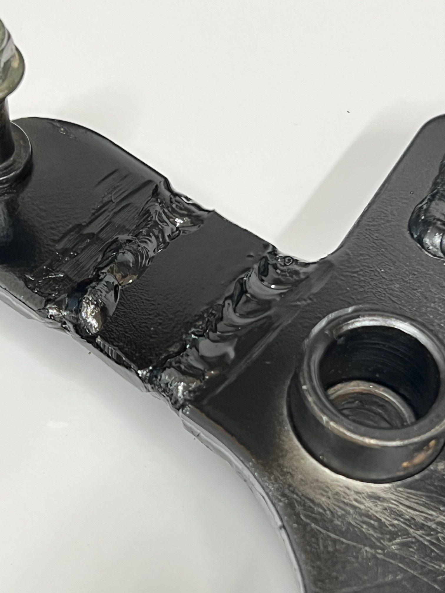
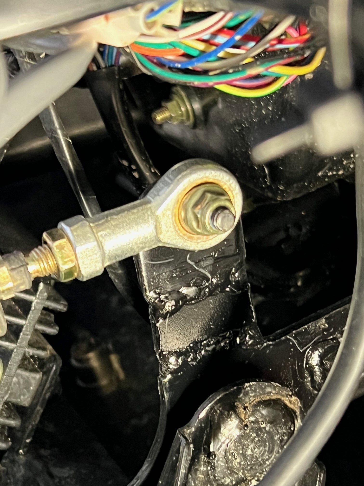
Hello again! I now have a pretty good running Coleman UT400 after a top end rebuild, wet clutch rebuild and a repaired crankcase... ! It plows snow great, but I was also having the jumping out of gear problem, mainly reverse, but a couple times out of forward. I would quickly place it in N and then let the engine idle down and shift again. This worked most of the time. I did some research and found that some have modified the shift linkage. The problem with just adjusting the shift cable is that it really NEEDS more throw, not an adjustment. From what I've read and viewed on the Internet, the linkage arm needs to be about 3/4" longer to gain more throw in both directions. On YouTube, the guy had to remove the shift linkage hole trim and notch the side of the dash to get the shift linkage off the pivot pin. BUT this is NOT necessary. When the "E" clip has been removed and you fish it out of the firewall somewhere, the shift lever is now loose. I had to pop the top of the shift knob off, remove the retaining screw and then heat the lower portion of the knob to get it to come off the lever. Once you have the shift lever loose, push it towards the right to slide it off the pivot shaft. But it won't come off just yet. Use a small pry bar/screw driver and slide the nylon flanged bushing out of the left side of the lever. This lets the lever slide off and get into a "loose" condition and it will twist and come right off without removing the dash trim, that could be a bugger to get back on correctly. Once the lever is off, press out the other bushing so when you're welding on the linkage arm, you don't melt the bushing. I found a piece of scrap metal the same thickness as the lever arm, just over 1/8" thick, close to 3/16". I cut my arm and beveled the edges for better welding. I added a piece just over 5/8" long and kept about a 1/16" gap between the arm and the new piece. Once welded on bother ends, it adds up to just about 3/4" or so. I reinstalled the lever after painting it and did an adjustment on the cable. By the way, it's easier to remove the cable from the bracket on the frame. This gives you more clearance to maneuver in that area with your hands. ALSO, you will need to get a 12" adjustable wrench and slide it over the cable mounting bracket and tweak, to the front, the steel so the cable is pointed upward a bit to now realign with the new longer shift arm lever. There's more than enough metal for the tweak and it will line up perfectly. I now bottom out the shifter on the transmission BEFORE I run out of throw on the shifter... I've tested it just a bit so far and it shifts much better with the longer throw. One of the Coleman authorized repair facilities said that he worked with Coleman to get a new part that's longer by 3/4". He's modified a few and it works perfectly for him. Just doing the cable will just short you on the other end. Here's some pictures of my modified shift lever etc.
2 points
-
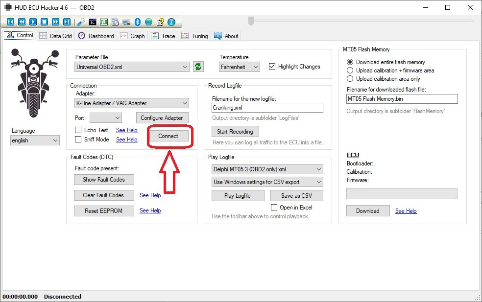
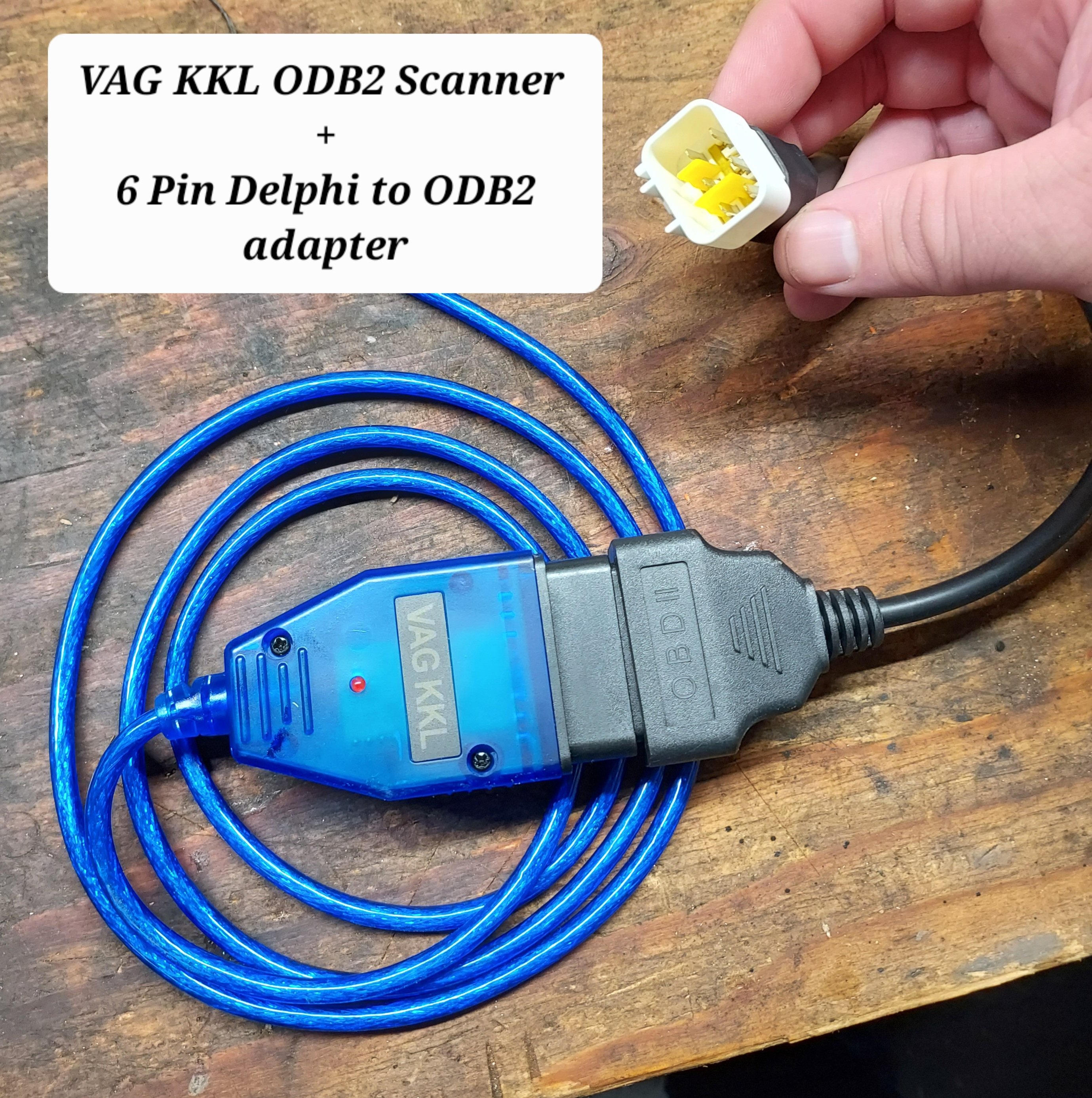
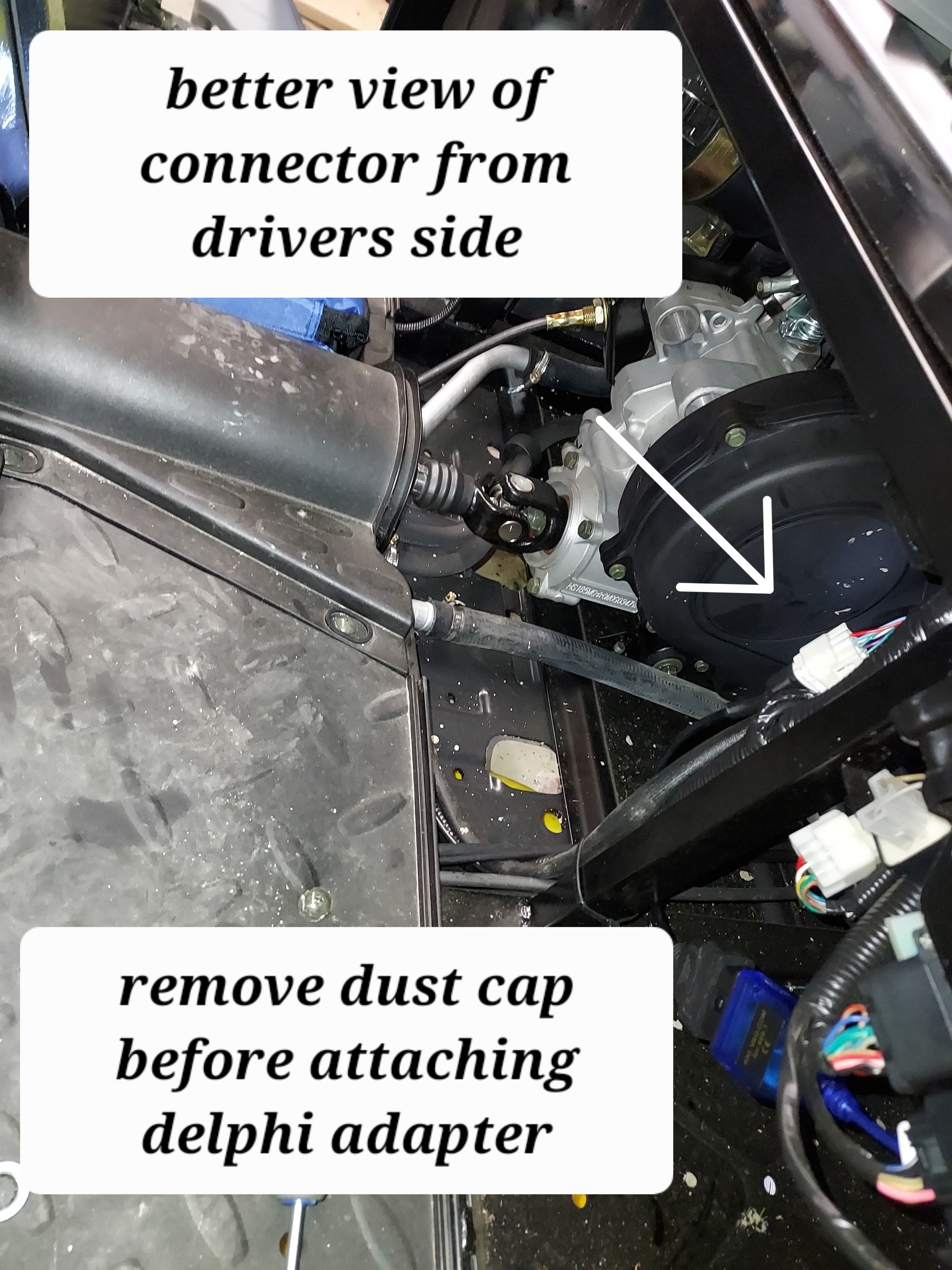
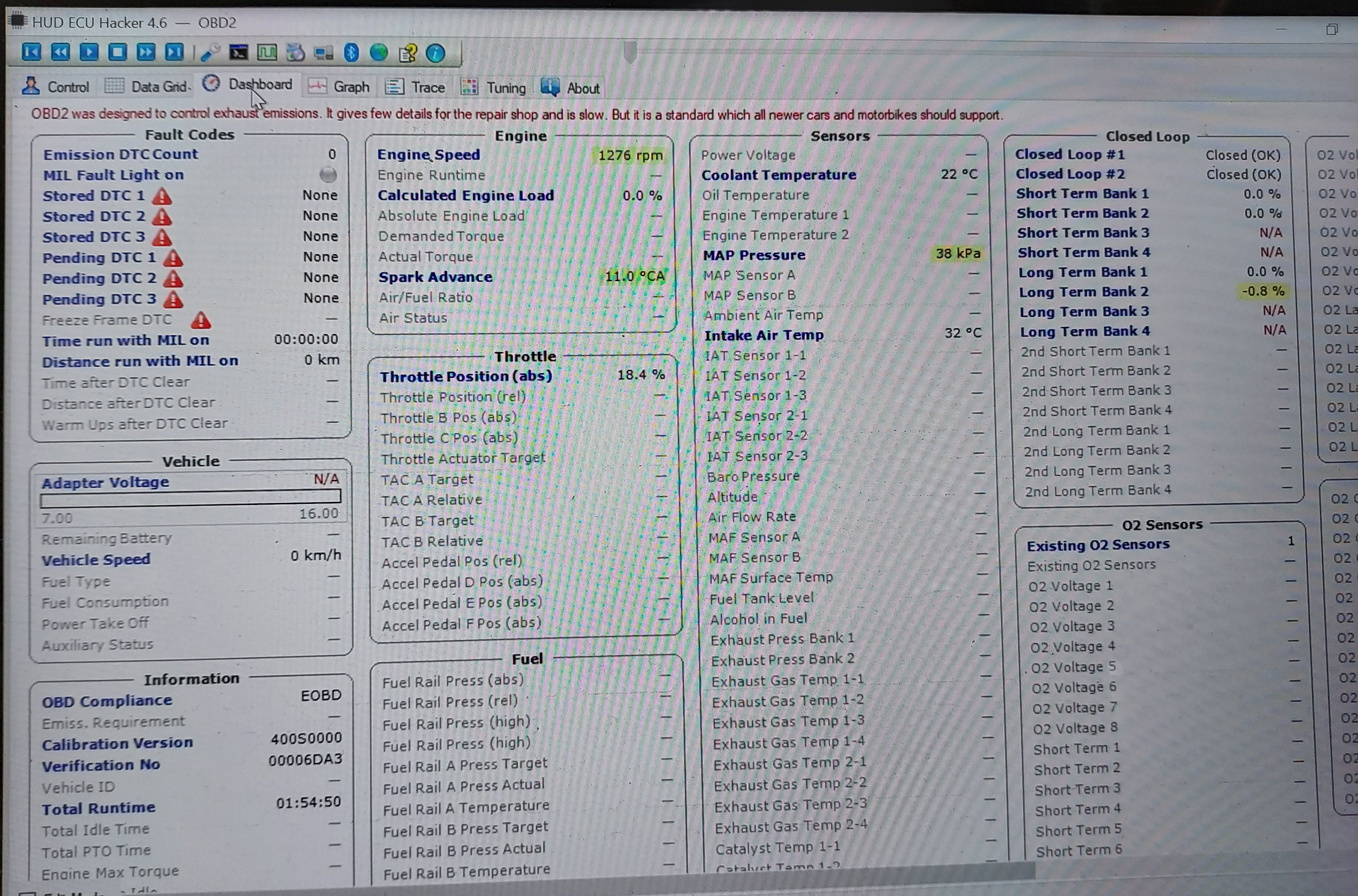
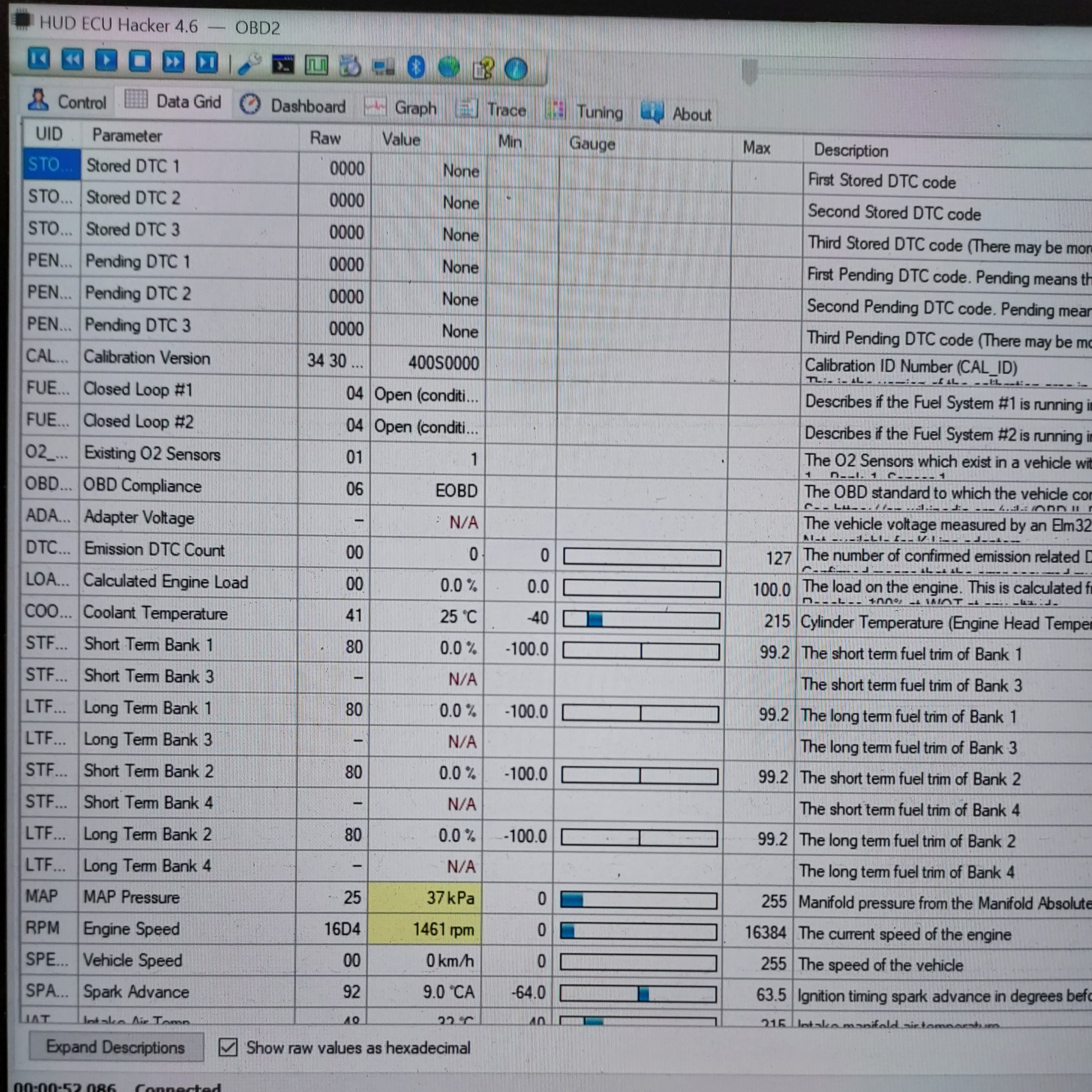
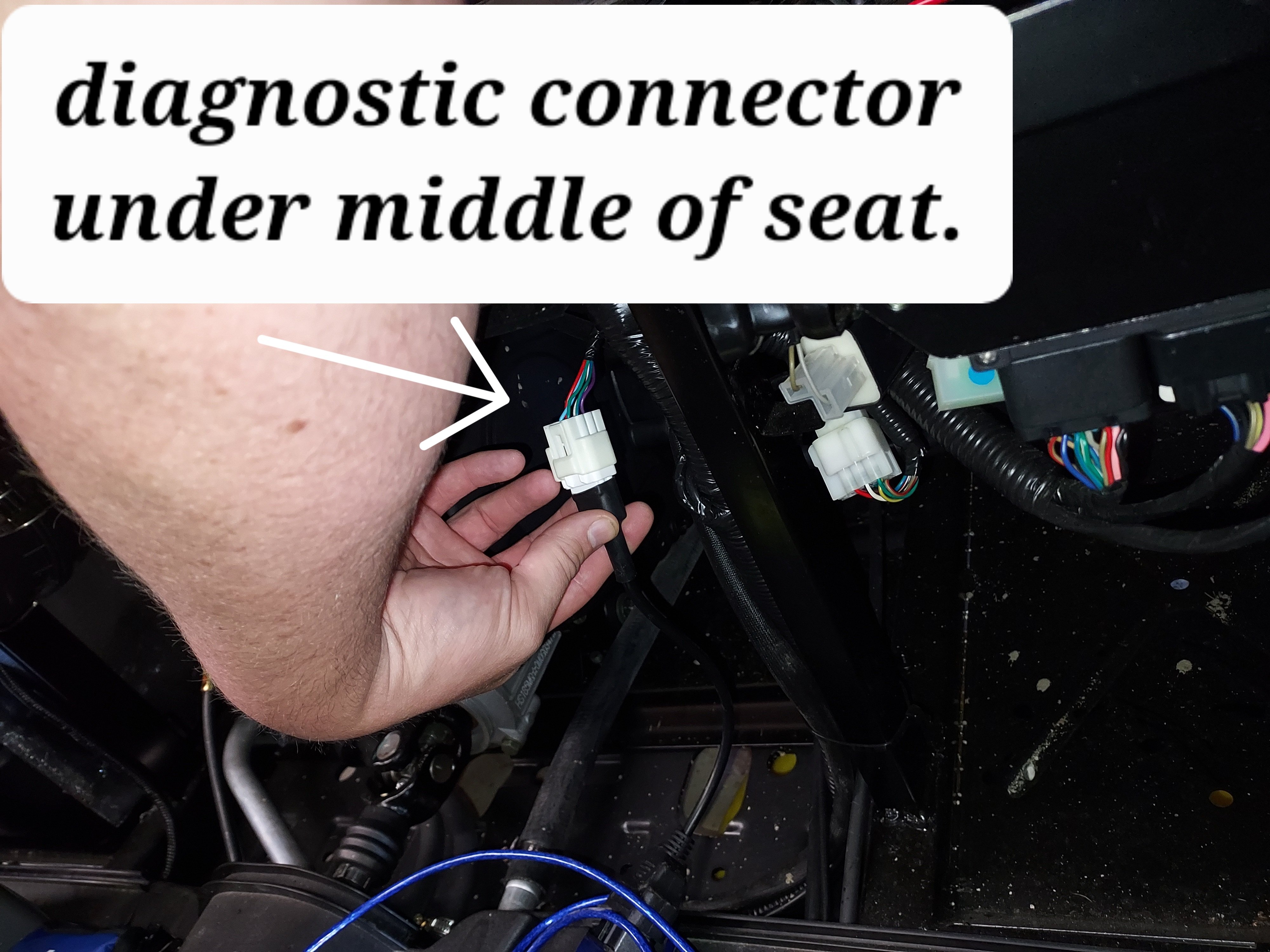
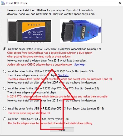
In order to connect with the ECU we need two cables. The first is a USB ODBII cable. HUD ECU Hacker’s documentation has a lot of different confusing options, but here’s what I went with and managed to get working, the cable is called “VAG KKL” it is a USB to ODB2 cable. It is available from a variety of sources for $10-15. The second thing we need is a “6 pin delphi to ODB2” adapter cable. It is also available for a similar price. In my case I ordered both from ebay, but there are other sources. Once we have our cable in hand we need to find the plug it in on your machine. My personal rig is a Coleman UT400, but the wire location should be similar for all Hisuns. My cable was located under the middle of the seat area. Just inboard of the battery, where the main wire harness split loom runs. The cable is a 6 pin (3x2) with a dust cap. Remove the dust cap and plug in the 6-pin end of the Delphi adapter cable. Note: When I was done, I left the 6-pin adapter connected, and zip tied it so it now runs to in front of the battery for easier access in the future. Next download and install HUD ECU HACKER DOWNLOAD Open HUD ECU Hacker on your PC It should prompt you to choose a driver to install. This particular cable uses the “CH340” driver (First choice on the menu) click to install, once installed hit the X in the corner to go back to the main page Once the driver is installed plug in the USB Cable, and plug the ODB2 end into the 6 pin adapter. The red led on the adapter should light up indicating it has power. Drop down and pick a com port on the main screen, it should show the VAG KKL adapter as a com port. Click connect on the main menu. It will pop up a bunch of fast scrolling text indicating it is connecting. Once connected you can click through the various tabs to see different data sets. The main menu also has the option to show fault codes, clear fault codes, reset the EPROM back to factory. The other function that may be helpful is recording a log file. You can record a log while operating the unit, and come back later and replay it to try to better diagnose what is happening. Within the various pages you will see the reading from each sensor. Sometimes a sensor reading will be off enough to cause running issues, but not enough for the ECU to realize its an issue. For example if the engine thinks it’s really warm, but its actually cold, it may not inject enough fuel to start. There are also more advanced functions, like adjusting fuel mapping, but that is beyond the scope of this tutorial. Full HUD ECU Hacker Documentation (Very technical reading) If you find this helpful give me a comment below or a thumbs up.
2 points
-
Yes! The U1 battery format is one of the shortsighted design issues in the 550 series. It is completely unsuitable for a UTV, but that is the hand we are dealt.I assume that you use the same battery in your 410. Just buy the biggest and best unit that will fit in the tray. I bought an AGM 350 CCA battery from Amazon. (ASIN: B0CKSKHDM6) There may be others that fit in that space, but my issue was resolved using the Sealed AGM (Absorbent Glass Mat) construction rather than the flooded lead acid design. And NEVER buy a N-EVERSTART battery from the Big Wally if you want to get home! 🏁1 point
-
The needle adapter shown in the first post makes it so you don't need to be straight perpendicular like with a traditional grease gun coupler, You need to make sure you're buying the blunt type like that, there are also sharp needles meant for piercing rubber in ball joints, etc. With the blunt needle adapter you basically shove it into the check ball. It does make a bit more of a mess than a normal coupler, but it does fit. The driveshaft zerks are certainly have limited clearance. The other option is a small grease gun that just fits on top of the zerk without coupling. You can see one pictured in the "rear driveshaft" pic Something like this1 point
-
DO NOT BUY MASSIMO OR ANYTHING HISUN... you have been warned. You will regret it. They are Chinese junk..1 point
-
Yes, please see what you can do. Now, ads are popping up on top of posts and I cannot shut them down, so I can't even read certain posts. I click on the X in the corner and the ad changes with an arrow in the opposite corner. I click on the arrow and the previous as appears.1 point
-
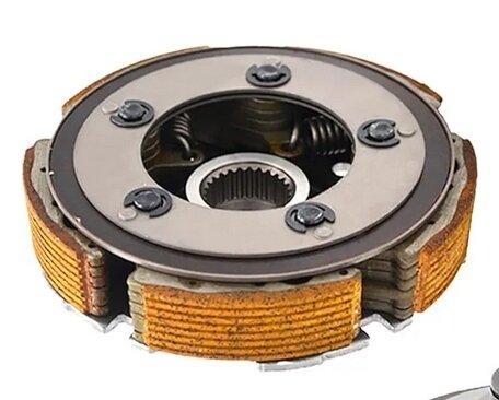
That's correct on the MA oil. Some of the info in that post is wrong. There are two things moving the power from the engine to the drivetrain: first there's a wet centrifugal clutch, from that drives the primary cvt pulley, which has a belt to the secondary. The friction material on the clutch is prone to slipping with use of additives "energy Conserving II" API rated oils, which are used in most car oils. Cars use a dry transmission, most motorcycles use a wet clutch where the clutch plates are bathed in oil. The MA rated oils don't have that additive which causes wet clutch slip issues. See attached picture of the friction disc of the wet clutch. Yellow stuff is the friction material. Once it starts slipping you get rapid wear, and also a lot of crud in your oil. Generally speaking conventional vs synthetic, synthetic oils have more uniform molecules and hence lubricate better and resist more wear and tear before going out of spec. They also typically have better additive packages, because the manufacturer expects them to be used for more mileage. Conv vs synth it makes little difference, and I would lean towards changing oil early on these machines being a large single cylinder ("thumper") they get more wear and tear than a normal car engine, and also I've read a fair number of timing chain stretching issues, which is typically an issue with accelerated wear of the pins holding the chain.
1 point
-
Rainman, Here are some of the posts. Pics included in them. https://www.utvboard.com/topic/13490-coolant-temp-volt-and-oil-pressure-gauge/#comment-53640 https://www.utvboard.com/topic/12598-cooling-fan-not-just-for-radiators/ https://www.utvboard.com/topic/13070-axis-air-box-elimination/ https://www.utvboard.com/topic/9395-2022-axis-same-as-hs500-seat-adjustment/1 point
-
Hi and welcome!!1 point
-

2 downloads
2022 Segway Fugleman Service Manual1 point -
Remove the spark plug. Rotate the engine until the piston is at the top of travel by using a copper wire (soft 10 AWG with rounded end down) and watch the travel up and down. When very close to TDC, the piston will stop going up and "stall" for a bit and then start to fall back down. Rotate "between these two positions" and you have TDC. Easier said than done. A dial indicator can also be used if you have the set up. Getting into the fan side is a pain with the cover.....bolt screw nut inserts usually "spin". Easiest is to take off the belt cover exposing the drive clutch pulley. On the rim of the pulley you can make an narrow ink mark (or tape with a ink pen line). Do the rock back and forth to find the "going up" and the "going down" location on the case. Mark the two locations. In the middle is TDC. Also, try to see if you can find the timing marks noted in the service manual and mark both with paint for future use. I had a simple trick (POSTED) to hold the chain in place and keep it from falling off the crank sprocket when installing the cam gear.....string pulled for a 3rd hand. I like to do a double check after timing the cam and then rotate to the OVERLAP (EXHAUST VALVE closing and INTAKE VALVE just opening) at the other TDC than Compression. Always rotate slowly by hand to check for valve interference. If something is wrong, you don't bend any valves. Rotate the decompression flyweights against the spring return to avoid being fooled by the cam's AUTO decompression mini-cam/button hitting the cam follower.1 point
-

From the album: California Nut case
1 point -
Just a idea about an senior and good aftermarket charging system company that has salvaged some new sales failures for a friend. Charging system puked in a few hours after purchase. That takes the shine off of a new unit. Rick's to the rescue. Design wise, the stator is made "light" on the windings so the regulator can be lower cost build....i.e.....cheap as is the "power runs in the OEM harness. The regulator used is a waste excess charging current system. The excess current is shunted to ground over and above that required for the 13.6V ish to charge the battery and run accessories. A higher wattage stator will need a higher wattage regulator. $$$$$$$$ We used Rick's for years.....the latest "problem" I heard about was a xmxmxmx unit that had a strong stator but the voltage regulator used for certain models dies and the regulator is on national back order. NEWLY SOLD UNIT IS UNUSABLE and NO LIGHT AT THE END OF THE TUNNEL. Rick's built up a "custom" regulator to fix the problem that xmxmxmx Engrs could not or would not fix. It is a multi-year screw up so there was time if Rick's worked up a winner in a week why not the OEM Engrs. Contact Rick's and spec a hotter stator and a matching better regulator. Warning: I have had to beef up the stator wires and regulator supply and gnd wires over the stock OEM wiring harness for some real headlights on street bikes.....too much drop in the cheap wiring runs. Just saying, you might have to do some harness upgrades also. Rick's Motorsports Electrics ricksmotorsportelectrics.com1 point
-
I have a 1999 Mule 550 which only had 25 psi on compression test. Leak down test indicated cylinder or rings issue, as I could clearly hear the air leaking when I removed the dip stick. Nothing out of the exhaust, & maybe a little out of the intake. I've removed the head, & there's a lot of carbon build up on the valves. I've ordered new valves, & am engine rebuilt kit, complete with piston & rings. When you pulled your piston, did you remove the engine, or were you able to remove the piston while the engine was in the frame? Thanks! I made the mistake of buying this sight unseen while I was deployed, & didn't think about asking for a compression test prior to paying.1 point
-
Would like to let everybody with the 23' Z Force units know that Spring Brake Thingy now has a parking brake available for these units. Pretty easy install, the brake pedal does need to come off for a couple holes to be drilled, but that's not all that difficult. These are all made here in the states, like all of our other models. see it at: http://springbrakethingy.com Mods: if we need to do something as a vendor please let me know, couldn't find any info and don't want to brake any rules......1 point
-
All made in China1 point
-
Turned out to be a faulty ignition switch.1 point
-
Yeah get the piston tdc and then adjust them but that was the problem with my 2019 550colman1 point
-
Your video is the tell.......you have belt rotation at idle Your belt is rotating AT IDLE with the primary sheaves.......that is a big NO NO. The rear sheaves (transmission input) always pinch and fit tight to the belt sides. The top of the belt is NORMALLY FLUSH to the outer rim of the rear or driven sheaves......your video looks like it is running "deeper" into the sheaves. The front sheaves should be open wide enough for the belt to flop (SIDE CLEARANCE at BELT EDGES) around when the motor is off and then sorta "drag the belt forward" BUT NOT PULL AND ROTATE until the engine Revs go up and thus tighten....as in close and pinch against the belt sides thus making the belt rotate. Go thru the motion of starting to remove the belt again. I assume you are using the rear hub squish screws to "open" thus get some belt slack. Now, in Neutral, with the belt loose, see if it will slip on the drive pulley. On other words, the belt will not "rub" on the sides meaning the front sheaves are opening wide enough for clearance at idle. Compress the rear pulley springs (open up the sheaves) and remove belt to test the action of the drive pulley. Start engine, run at idle, then raise RPMs and watch the drive pulley sheaves collapse together....get narrower....with increased Rs. Drop throttle and the sheaves should return to the wide open distance at idle. I have seen where the cords from a blown/shredded belt get under the shaft bearing (the cylinder sleeve that you see between the drive sheaves) and restrict the required sheave distance travel. If this is the case, the drive sheaves won't open enough and drag tension on the belt and "pull it deeper into the rear pulley"......which the video shows. Like buying the wrong belt and it is not long enough. Take the belt and lay it around only the rear pulley. See if it will ride at the top of the sheave rim with the squish bolts removed. If it does, your problem is with the front or a wrong belt. The drive pulleys spring will REACT to the belt tension. More tension pulls the belt in DEEPER...and that is how it works.....all controlled by the engine RPM and flyweights at the front drive pulley. Speaking of flyweights and the slide bushings wear will also limit the travel of the drive sheave width. Next, load the belt into the front pulley. It should sit deep into the sheaves and have side clearance to where you can pull the belt freely back and forth. BTW, older Polaris drive pulleys had a grooved inner bearing sleeve and the OEM belt had matching grooves in the inside. Some aftermarket belts had the grooves BUT the number and spacing was off....that small amount of "extra material" would cause the belt to drag and pull at idle.....let off brake and away it goes. Bottom line, it is a juggling act for the whole setup to work.1 point
-
Maybe a dumb question, but do you have your foot firmly on the brake pedal? Mine would do the same thing, unless I pressed hard on the pedal. I did some adjustments to the brake switch, and the problem was solved.1 point
-
while i didn't eliminate the box, i did relocate the intake to the back of the passenger side and added a motorcycle filter for extra measure... seems to be working so far1 point
-
I still say if manufacturer didnt want you to DRAIN the oil and wanted you to vaccuum it out thru the dipstick, they would not have installed a DRAIN PLUG! just sayin1 point
-
I just did an oil change on one for a customer. I would for sure drain especially for the first time. the pickup screen behind the plug was 90% plugged with pieces of rtv from assembly and pieces of block casting. if this just got sucked out it would have lost oil pressure very soon. I agree sucking oil out works in some cases but with this type of filter system it should be drained from the plug.1 point
-
Sounds like the TSC people didn't really know the full story behind it. Those places, and others, do have a frequent turnover in workers. If it is all you can afford, and you think you can get everything up to par without a lot more money and time, then probably should keep it. Deliberately scamming someone versus not knowing all the real details are different things to me. As Charles said above you should be able to find parts pretty easily without a huge price tag. I would definitely replace all the fluids and oil filter just to be safe.1 point
-
most likely translation error, I have the massimo wet clutch oil1 point
-
Buy new and buy quality. Otherwise you will have to spend your time sharpening your mechanic skills. Good luck.1 point
-
This is why Kawasaki has a 3 year warranty. you're still within the warranty period, i'd let the dealer perform any adjustments it may need.1 point
-
I can see how that would help, but in the lever there is a machined/cut cam slot that the detent ball rides on. If you "over stroke" the shift lever, you are now trying to raise the detent back out. I get why you did this, but in my case, having the same issues, I elected to do the shift lever extension of 3/4". I posted the thread prior and pictures of what I did. With the approximate 3/4" longer lever, you get the added throw in both directions and still stay well withing the detent ball alignment. Even if you cannot do the welding yourself, remove the shift arm and take it to be lengthened. Reinstall it and you should be good to go, of course with the proper shift cable adjustment. This DOES NOT eliminate any internal issues you might have in the shifter assembly at the transmission. "MOST" of us only have the "too short of travel" issue and the longer shift are does take care of that without any modifications to the hole in the dash or bezel for the shifter. I think a couple people here have had internal problems and of course the shifter cable travel will NOT help. The detents on the shifter still allow for proper movement and the F/N/R light works as it should. Good luck with your fix and hope it remains a fix for you. I know mine has a good solid fix as I've plowed this winter with it several times and pushed some big drifts with it. Before I did the shifter extension, it would jump out of reverse most of the time I needed to give it a bit of throttle. The second snow storm I had the fix done and the remainder of the winter and even now, no issues. Again, good luck and a few pictures of your modifications might help others here. Thanks for posting, Dan1 point
-
Gotta agree. I can't see how a siphon pump will extract everything. Drain and fill is the best method.1 point
-
Just out if curiosity how many miles/hours did you put on it? What exactly are they saying the issue is? Frequently commercial use shortens or negates warranties so that doesn't entirely surprise me.1 point
-
Well I have definitely got the same problem bought it brand new a 2018 cub cadet challenger 750 and have had it 2 years now haven’t been able to ride it more then a couple weeks at the time only 200 hours in and has a new timing chain tensioner all new clutches wet primary and secondary new belt new weights new spring new water pump new exhaust and it still over heats after 5 minutes of running1 point
-
Dont recall the name of it.. I just Googled UTV engine rebuilders ..Picked one, I emailed the Owner.. he said he was 99% sure one of his YAMAHA rebuilts would bolt up where my HISUN is now.. The Hisun is a Yamaha CLONE.. .. He also said it for any reason it did not, he would take it back.. He also had free shipping .. If mine fails again, I will likely go that route . Currently mine is still running1 point
-
That is just normal operation and the same with cars and trucks! But the issue is with these the firewalls are not insulated!!! so we feel it1 point
-
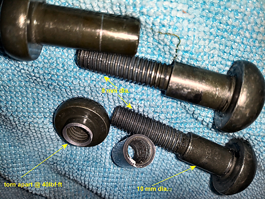
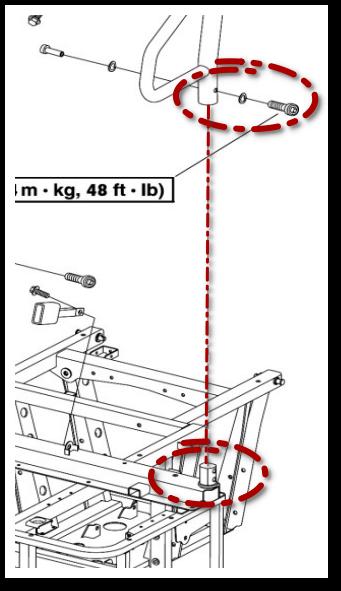
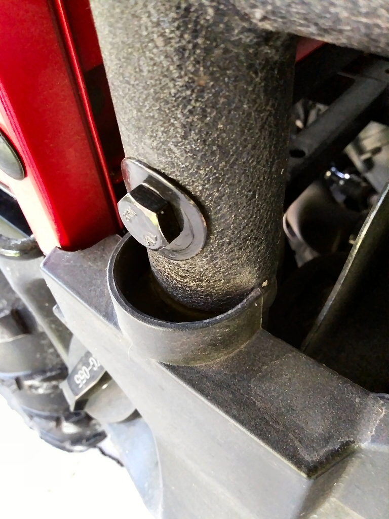
I have been meaning to write this up for some time. As delivered (in late October 2020) my 2020 UT400 had the expected number of loose "final assembly" nuts and bolts, but even after tightening down everything it still had an annoying metal-on-metal rattle--one f those that was quite audible but difficult to locate. it sounded like some chassis or suspension component but I could not pin it down. So, I took to carrying a large rubber mallet with me and stopping and banging on things when it really got to me. Eventually I tracked it down to the rear uprights for the roll cage moving about on their mounting posts. The left and right rear cage posts slip onto forged steel hubs welded to the frame and were cross-bolted with some very pretty 10 mm dia. binding post type fasteners having an 8 mm threaded internal shank (the Service Manual says they should be torqued to 48 lbf·ft but when I tried all I got was a violent and quite loud "pop" as the head ripped off the female end): Examine the torn apart section and it's obvious why it could not handle 48 lbf·ft. Here's how it mounts, from the service manual; So, I replaced both binding bolts (pretty but not up to the task) with a plain ol' 10 x 1.25 x 50 mm class 10.9 bolts and self-locking nuts; and had at torquing it again--no problems, the cage upright squeezed up tight on the forged post and the rattle was gone making me a "happy 'UTVer'"...
1 point
-
217 downloads
I got this from Coleman, detailed instruction re: shift cable adjustment...1 point


This leaderboard is set to New York/GMT-04:00
