


Leaderboard


Popular Content
Showing content with the highest reputation since 03/24/2022 in all areas
-
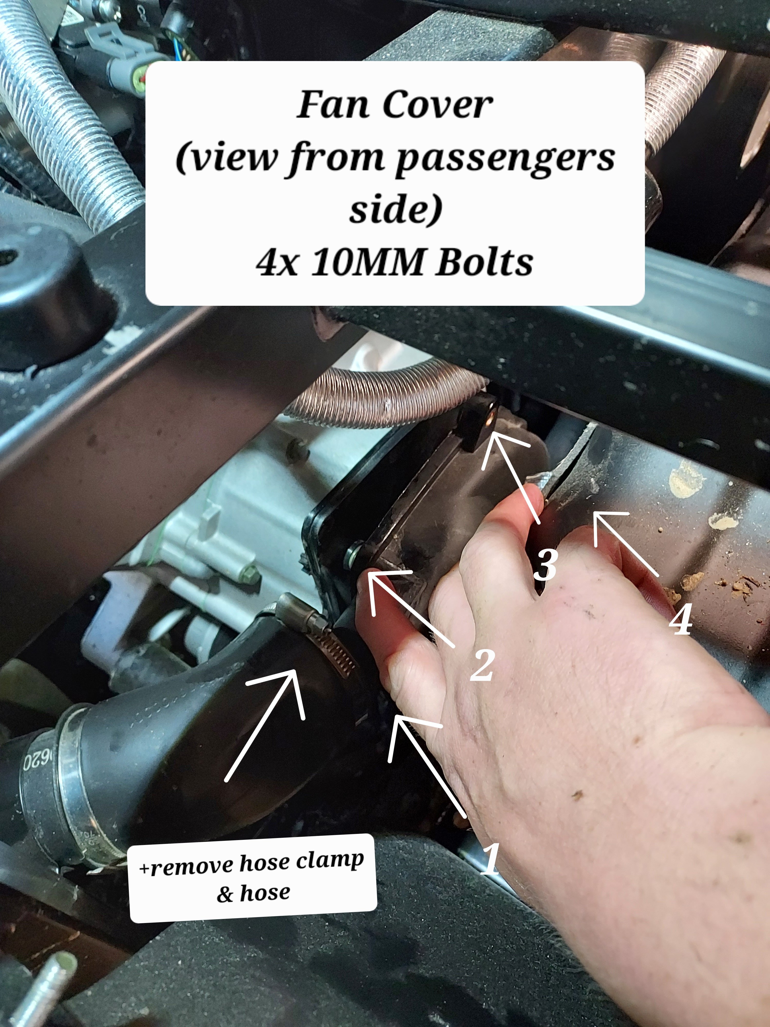
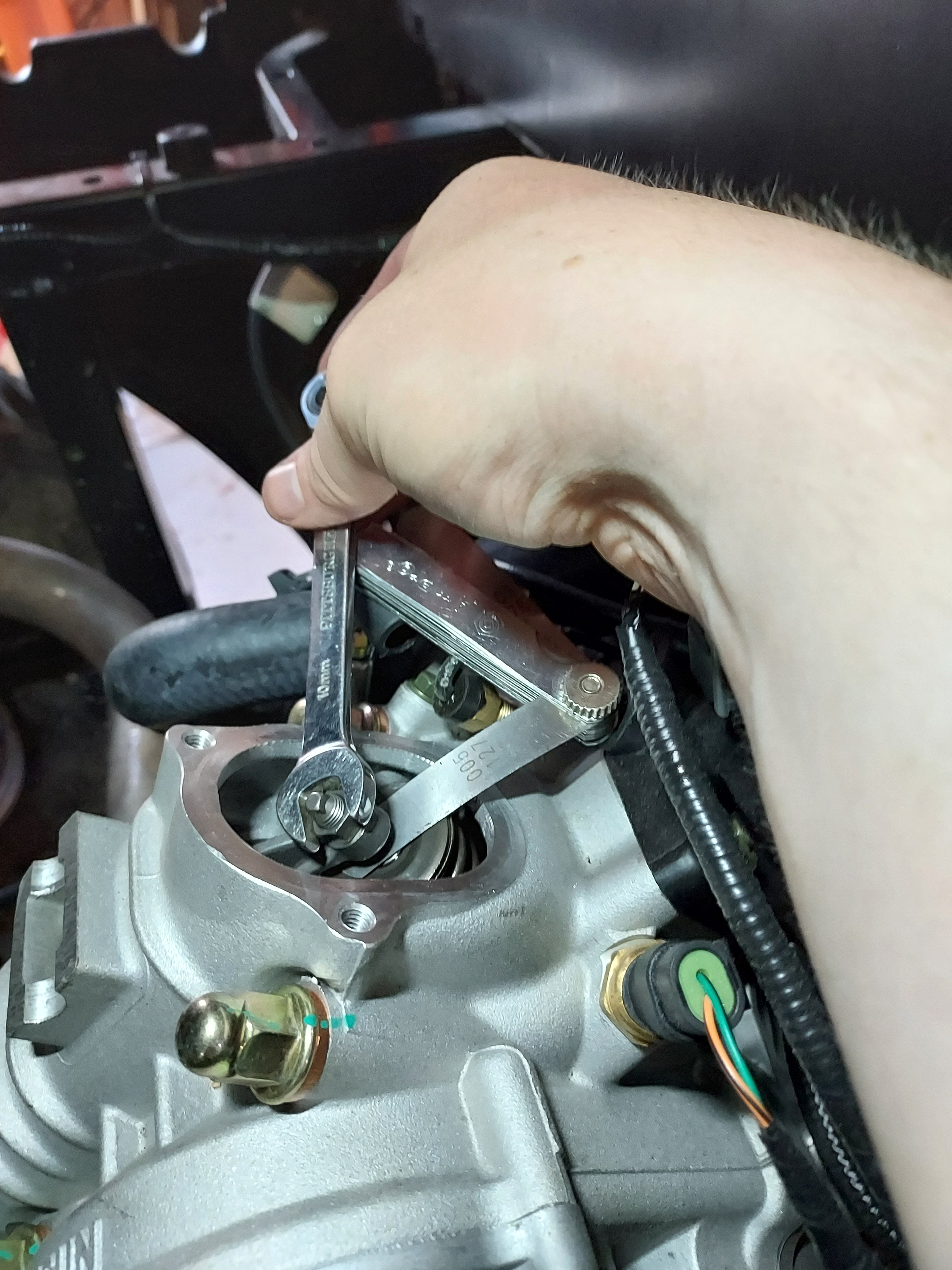
Since I've seen some questions on this I took some pictures and will provide instructions on a valve adjustment for the UT400. This should be the same for the 550's and other various Coleman/Hisun single cylinder models with the cylinder slanted aft. I have seen several people ask of it is really necessary, and read several reports of valves being out of adjustment from the factory. My valves were .004" intake, and .010" exhaust with about 5 hrs on the machine. I've seen different numbers thrown around for factory spec, but I decided to go with 0.005". This is called valve lash. What is is is a gap between the rocker arm and the valve then the camshaft isnt opening the valve. Why does it matter? If it's too large the valve doesn't open all the way, if it's too small the valve dosent close. This can cause valve damage (overheating) as well as loss of engine power (burned fuel is going out exhaust rather than pushing the piston dow). Tools required : 5MM Allen wrench, 10MM box wrench, needle nose pliers, flat feeler gauge set, rags First you need to remove the fan cover on the passenger side. There is a cooling vent hose on the back side, remove the hose clamp and slide it off. From there there are 4x 10mm bolts holding the cover. The forward ones can be accessed from under the seat. Next remove the spark plug from the drivers side. Carefully wiggle the spark plug wire off. Grip it as low as possible and give it a little twisting motion as you pull it off to help free it. Its a tight fit for a socket, but there is a sheet metal wrench in the toolkit that fits it. Unscrew the plug and set it aside. This allows you to spin the motor over freely with no compression to fight. When you reassemble this is a good opportunity to switch to an NGK iridium plug for better performance/less fouling DR8EIX) Next you need to remove the intake and exhaust valve covers. The intake us the forward one. There are 3x 5MM Allen screws to remove. The Exhaust is the rear with 2x 5MM Allen bolts. Both covers have O-Rings instead of gaskets and are reusable. When you remove the rear be careful and use your rags as there will be oil that drips out. Next up we need to spin the motor over to top dead center. Grab each rocker arm and give em a little wiggle up and down. Spin the engine over by grabbing the fan with your other hand. Spin the engine over until both rockers have some wiggle and are loose. Once both rockers are loose slide the feeler gauge in like shown above. Try different feelers as needed to determine your starting spec. You should feel some drag but still be able to move the feeler without too much force. If you need to adjust, use the 10MM wrench to slightly loosen the locknut, then with the correct feeler gauge in place, tighten the top square nut while wiggling the feeler in and out. Once you have it right you need to tighten the 10mm lock nut without moving the square head bolt. Once the lock nut is tight recheck the clearance. That's it, button everything back up and make sure you have it all reassembled before running it again. If you find this helpful give me a thumbs up or comment. If you have any questions or need more help let me know. If there's interest maybe I'll do some more of these
 8 points
 -
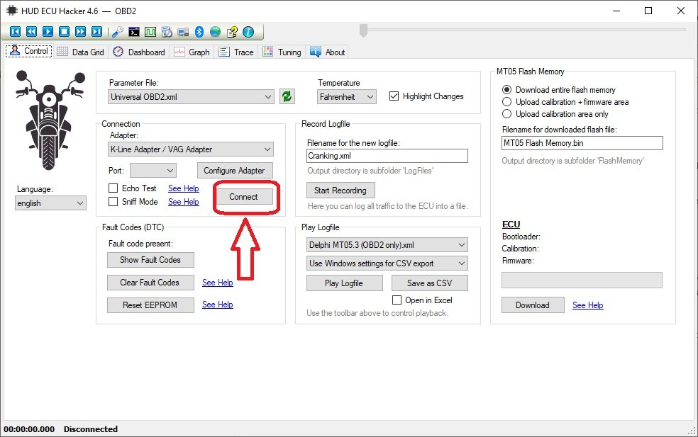
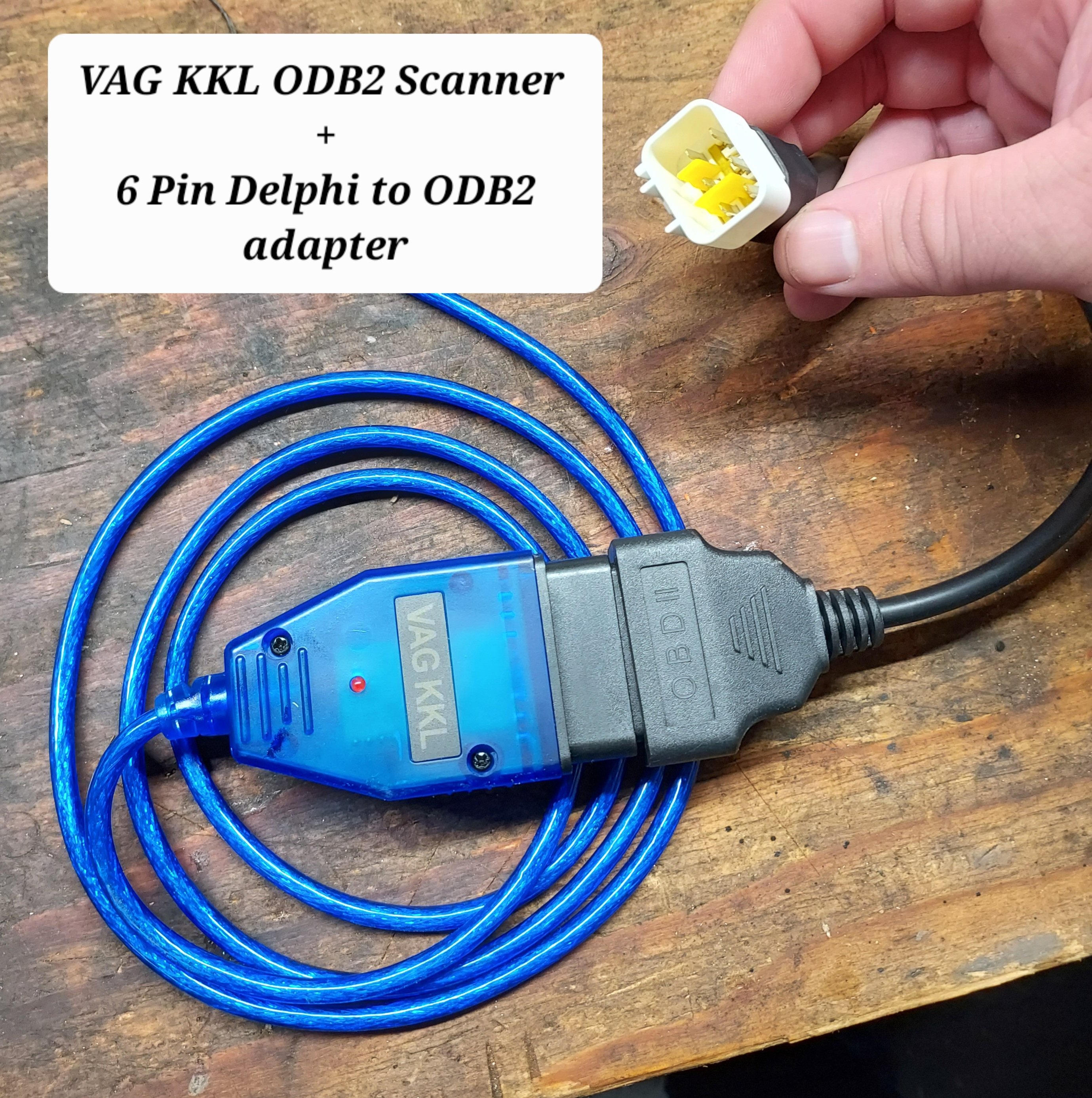
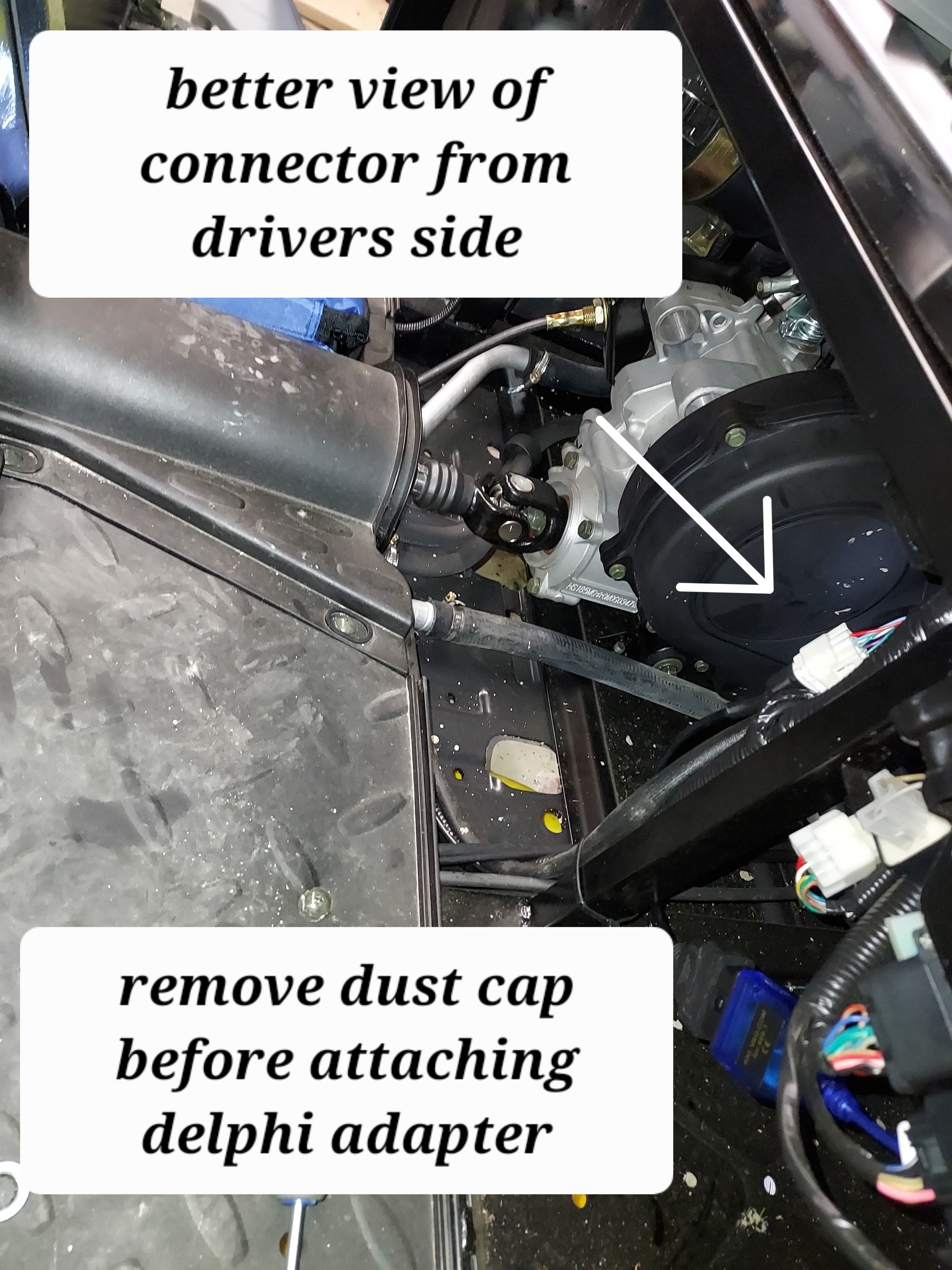
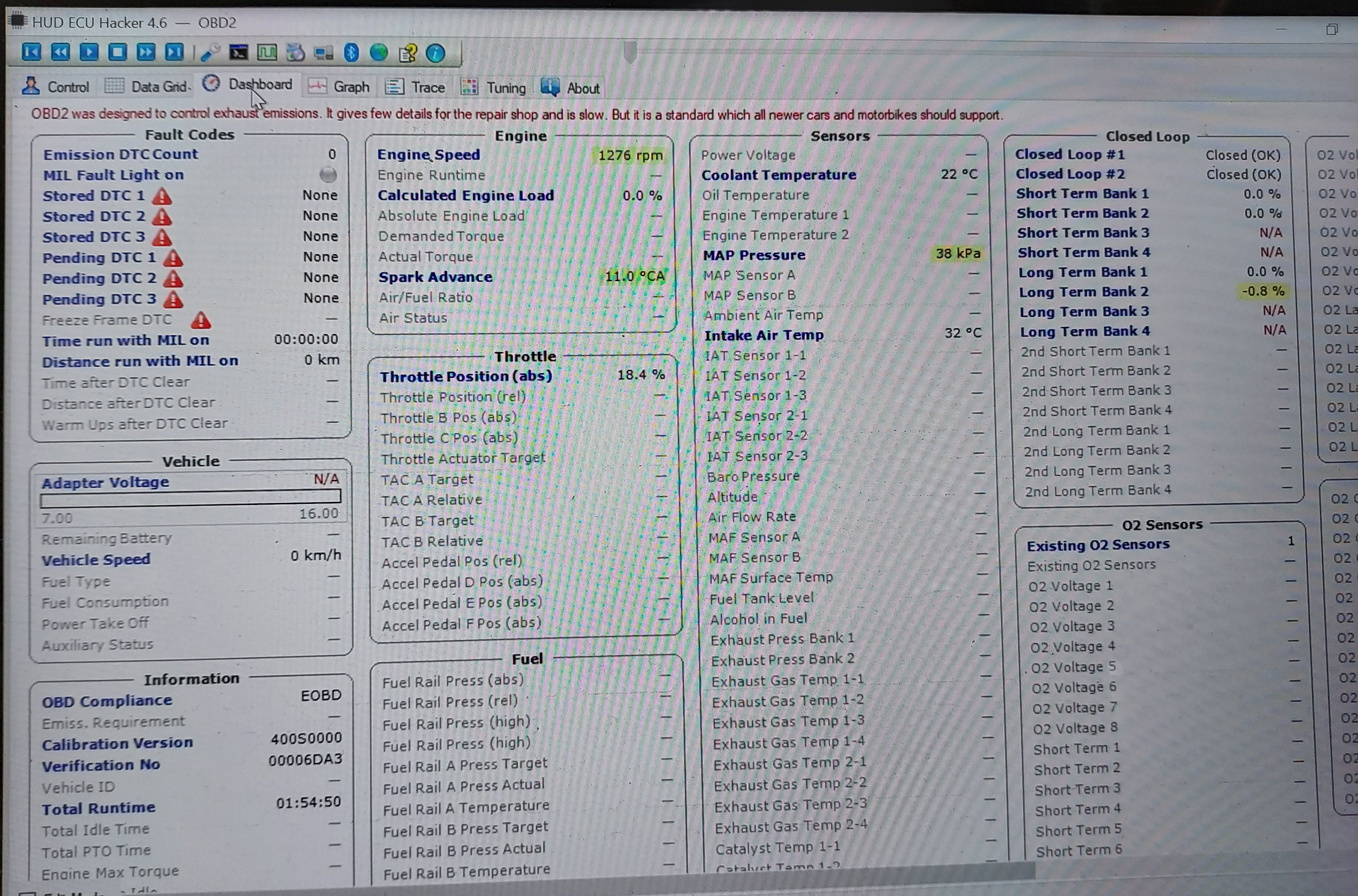
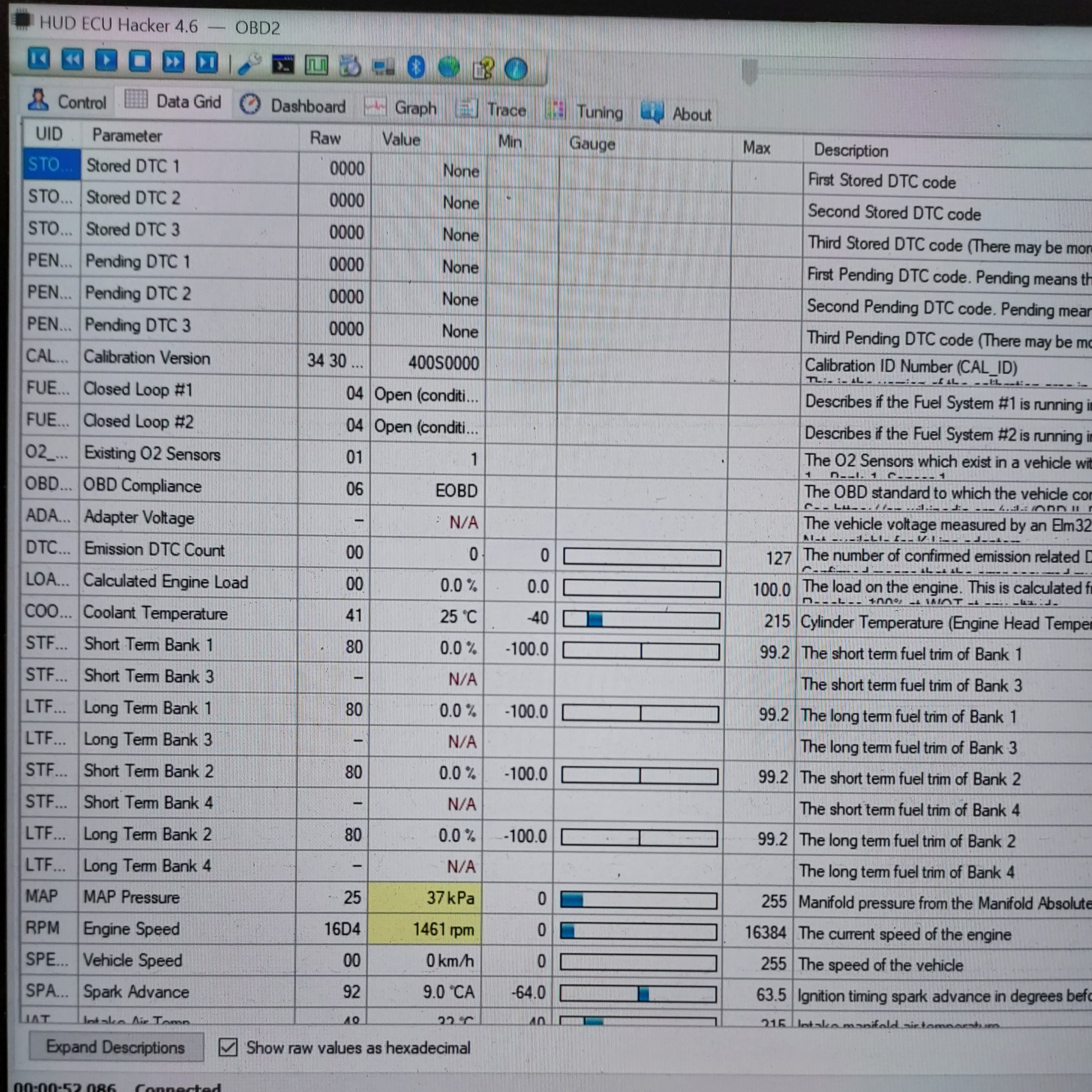
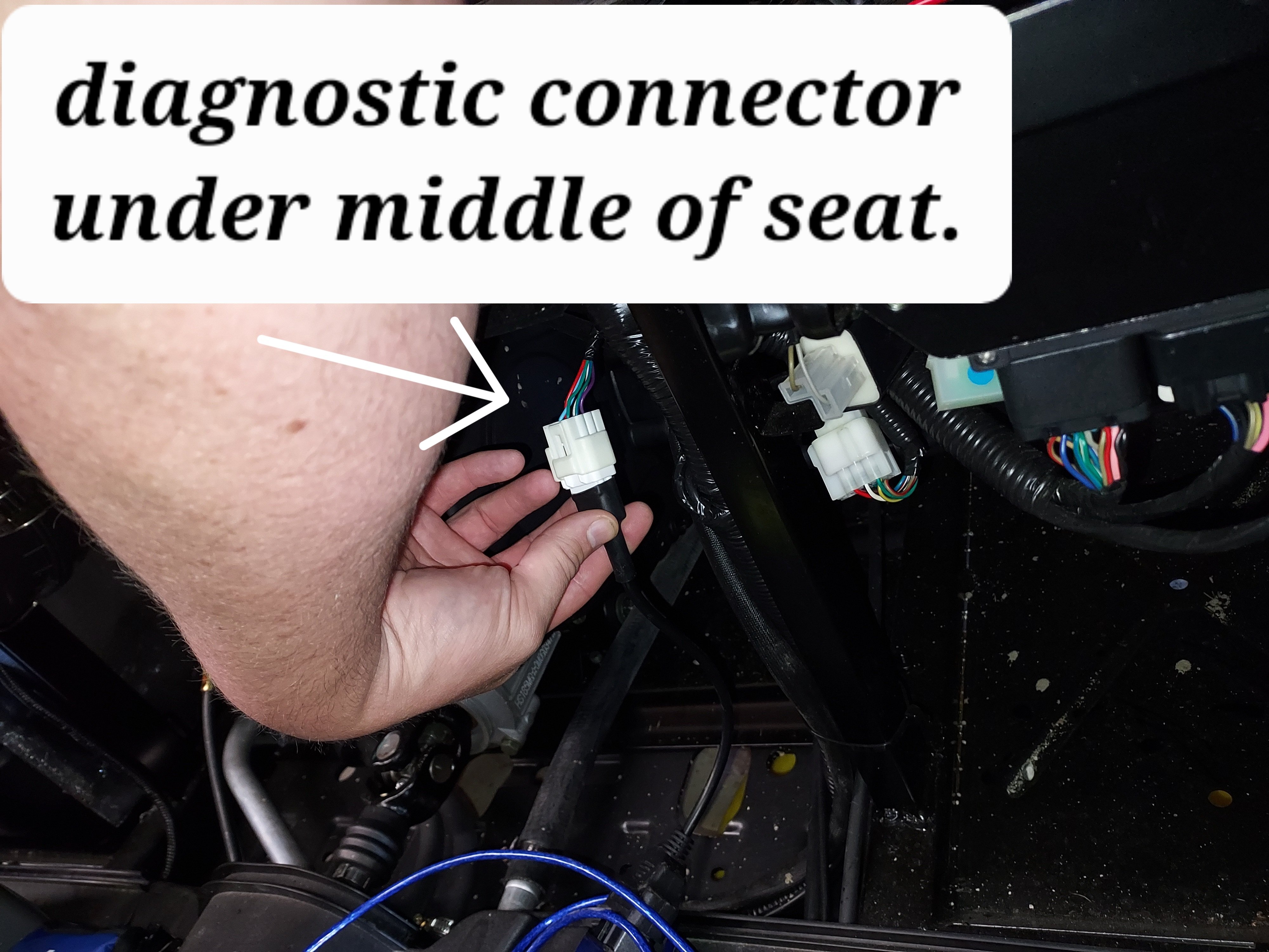
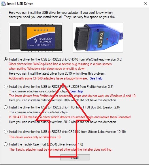
In order to connect with the ECU we need two cables. The first is a USB ODBII cable. HUD ECU Hacker’s documentation has a lot of different confusing options, but here’s what I went with and managed to get working, the cable is called “VAG KKL” it is a USB to ODB2 cable. It is available from a variety of sources for $10-15. The second thing we need is a “6 pin delphi to ODB2” adapter cable. It is also available for a similar price. In my case I ordered both from ebay, but there are other sources. Once we have our cable in hand we need to find the plug it in on your machine. My personal rig is a Coleman UT400, but the wire location should be similar for all Hisuns. My cable was located under the middle of the seat area. Just inboard of the battery, where the main wire harness split loom runs. The cable is a 6 pin (3x2) with a dust cap. Remove the dust cap and plug in the 6-pin end of the Delphi adapter cable. Note: When I was done, I left the 6-pin adapter connected, and zip tied it so it now runs to in front of the battery for easier access in the future. Next download and install HUD ECU HACKER DOWNLOAD Open HUD ECU Hacker on your PC It should prompt you to choose a driver to install. This particular cable uses the “CH340” driver (First choice on the menu) click to install, once installed hit the X in the corner to go back to the main page Once the driver is installed plug in the USB Cable, and plug the ODB2 end into the 6 pin adapter. The red led on the adapter should light up indicating it has power. Drop down and pick a com port on the main screen, it should show the VAG KKL adapter as a com port. Click connect on the main menu. It will pop up a bunch of fast scrolling text indicating it is connecting. Once connected you can click through the various tabs to see different data sets. The main menu also has the option to show fault codes, clear fault codes, reset the EPROM back to factory. The other function that may be helpful is recording a log file. You can record a log while operating the unit, and come back later and replay it to try to better diagnose what is happening. Within the various pages you will see the reading from each sensor. Sometimes a sensor reading will be off enough to cause running issues, but not enough for the ECU to realize its an issue. For example if the engine thinks it’s really warm, but its actually cold, it may not inject enough fuel to start. There are also more advanced functions, like adjusting fuel mapping, but that is beyond the scope of this tutorial. Full HUD ECU Hacker Documentation (Very technical reading) If you find this helpful give me a comment below or a thumbs up.
6 points
-
White smoke is usually coolant leaking into the cylinder. Sounds like a blown head gasket to me.4 points
-
Since it's designed to go thru mud and water, I can't see how you can hurt it .Just don't spray into the air filter box.I pressure was my UTV and Atvs after each use to prevent corrosion3 points
-
Hi Space Ghost and welcome. I'm one of the originals here but don't post much these days. After reading your posts I feel obliged to reach out to you. Firstly thanks for your service and the sacrifices you've made. We are a Powersports Dealer and can and will give you at least a 10% discount on parts and accessories you may need. Contact other Powersports dealers and they will help you too. You deserve to get the best deals going. Contact me at any time and just mention UTV Board. Thanks, Mike.3 points
-
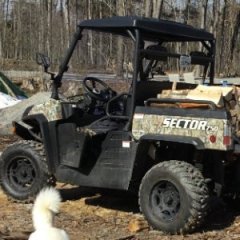
My Service dog Bärli on the left with his battle buddy Louie on the right.
3 points
-
Welcome Space Ghost, I too just upgraded from a quad ATV to a full cab UTV. For many of the same reasons as you. My service-connected disabilities make it very difficult to ride and be out in the elements anymore. The new UTV is making riding still possible. Thank you for your service!3 points
-
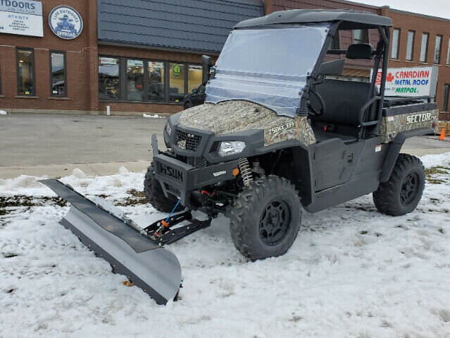
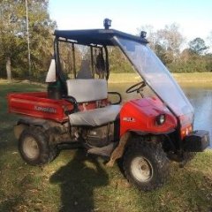
Not sure if this would be an option for your 550: I'm using a 72" KFI plow on my Hisun Sector 750 - works well. Driveway is 350'+ x 12'. One pass down the middle and then one on either side. (photo is UTV with plow at the dealer's - was delivered that way). Note - need to manually adjust plow angle.
3 points
-
if i cannot see, feel, operate a piece of equipment, i am not interested..............3 points
-
I was reading through an old thread about the woes of the risky ownership of Hisun UTVs. Well, OK. So we all own some problematic machines. But I’ll say this. I’ve owned bicycles, automobiles, snowmobiles, PWCs, boats motorcycles, class 8 trucks, airplanes and a crapload of heavy equipment. Nothing I’ve owned and operated hasn’t broken or needed maintenance. The difference between all those prior items and my Hisun, I feel, is the support (or lack of)from the factory and dealership. That’s where this and other forums come in. We’re all we have! Well, us and YouTube. Oddly enough though, with help I’ve received from YouTube and you guys,I’m actually starting to enjoy crawling through this machine, and screw the factory/dealer. I’ll make this vehicle what they didn’t. And have fun doing it.3 points
-
I thank you PB3 points
-
Did you take a look at the parts diagram?...https://alpha-sports.com/massimo_parts.htm?q=massimo-parts I suppose there may be a unique situation that only a 1 off bolt or screw may work, but everything I see on the parts diagrams are standard metric bolts. They are after all trying to minimize costs, and creating unique hardware hardly seems productive.3 points
-
Hisun Sector E1 Discovery to Lithium Conversion. So I went ahead and did the conversion using the LiTime 4-pack 48V 30Ah GC2 which I ordered on Amazon Prime Day for $1840 ($460/battery). Also bought the LiTime 58.4V 18A ($200) Lithium Battery Charge and “Superboni” 7pc set #2 Awg HD Golf Cart Battery Club Car 48 Wire Kit ($56). I utilized the LiTime charger to activate the Bluetooth and charge each battery to full. Then, connected them all in parallel and allowed them to balance both internal cells of each battery and between batteries which took several hours. Removed all the old Discovery batteries which as stated before requires the removal of the front panel under the seating and is much easier if you disconnect the piston allowing the rear bed to open fully. Placed the 4 new batteries in the most interior positions and had to utilize the braces from the exterior positions because the H-brace from the interior positions overlapped the battery terminals on the new batteries. Be sure to position the batteries so the original connections can reach which for me was positioning the negative terminal on both posterior batteries towards the rear. I connected the batteries in parallel for balanced but not perfectly balanced charging/discharge because it would require connections crossing over the controller sitting between the left and right battery positions. Basically, the connections followed a “U” pattern around the controller. I used this webpage to help wire the batteries: https://www.solar-electric.com/lib/wind-sun/Iota_balanced_charging.pdf I reprogrammed the Delta-Q charger to profile #233 charging to 56V as previously mentioned by Jaime since I read it is not recommended to utilize the max charge voltage which would have been profile #386 charging to 58.4V. https://support.delta-q.com/hc/en-us/articles/14188856858893-Choosing-an-Algorithm-for-a-Lithium-Battery How to upload new profiles: https://support.delta-q.com/hc/en-us/articles/360015622531-IC-Series-How-to-reprogram-reflash-or-upgrade-software-and-algorithms-via-USB How to change charger profile: https://support.delta-q.com/hc/en-us/articles/360016475772-Changing-Algorithms-on-IC-Series-Chargers Download profiles here: https://support.delta-q.com/hc/en-us/articles/360015622311-Download-Algorithms-for-IC-Series-Chargers Put everything back together and took it for a test run. Everything appeared to function properly and certainly has more power. I am using the battery Bluetooth with the LiTime App to monitor the batteries individually and the App has a feature that allows you to monitor all 4 batteries as a system. I was able to see that the batteries did charge on the Delta Q charger as well. It’s been less than a week, so I will update if anything changes, but overall for less than $2100 + tax/shipping(free since I have Amazon Prime), I’m very happy with the conversion. Hope this helps anyone else thinking of making the leap to Lithium.3 points
-
there was a time I could say my HAIR would protect my head... not any more3 points
-
Stay away from Chinese UTVs.Service is non existant.They don't honor warranty. I personally like HONDA for their durability .3 points
-
Hello to anyone who reads this. I am Jon and I own J&M Outdoor Power, a very small, small engine repair shop. I was approached by Coleman about 6 months ago to become one of their Warranty Centers. I recently received 3 different UT400's and a UT500 all with similar issues. These units range from 2 months to 2 years old. Customers state that the unit(s) was/were running fine, then heard a pop and a loss of power, two would no longer start. The two that would run would not achieve normal operating speed (around 20mph I would say) without redlining the RPMs. I quickly found that the Valve lash on each unit had become too large on some(both intake and exhaust) and too tight on one(just intake). After setting the gaps to .005(I found multiple different people suggesting bigger and smaller gaps, but no definitive Coleman Spec number yet) every unit starts, runs, and achieves top speed without issue. I don't know how many others have come across these issues, and I wanted to get something out on the web for others in the same predicament. Please let me know if you have had similar issues. Edit: I realize that this will not be a fix all solution for this issue, as the oil level and condition should be verified before moving to the valves. Many times improper oil conditions will cause valve lash to change. These units all have good oil and proper oil changes.3 points
-
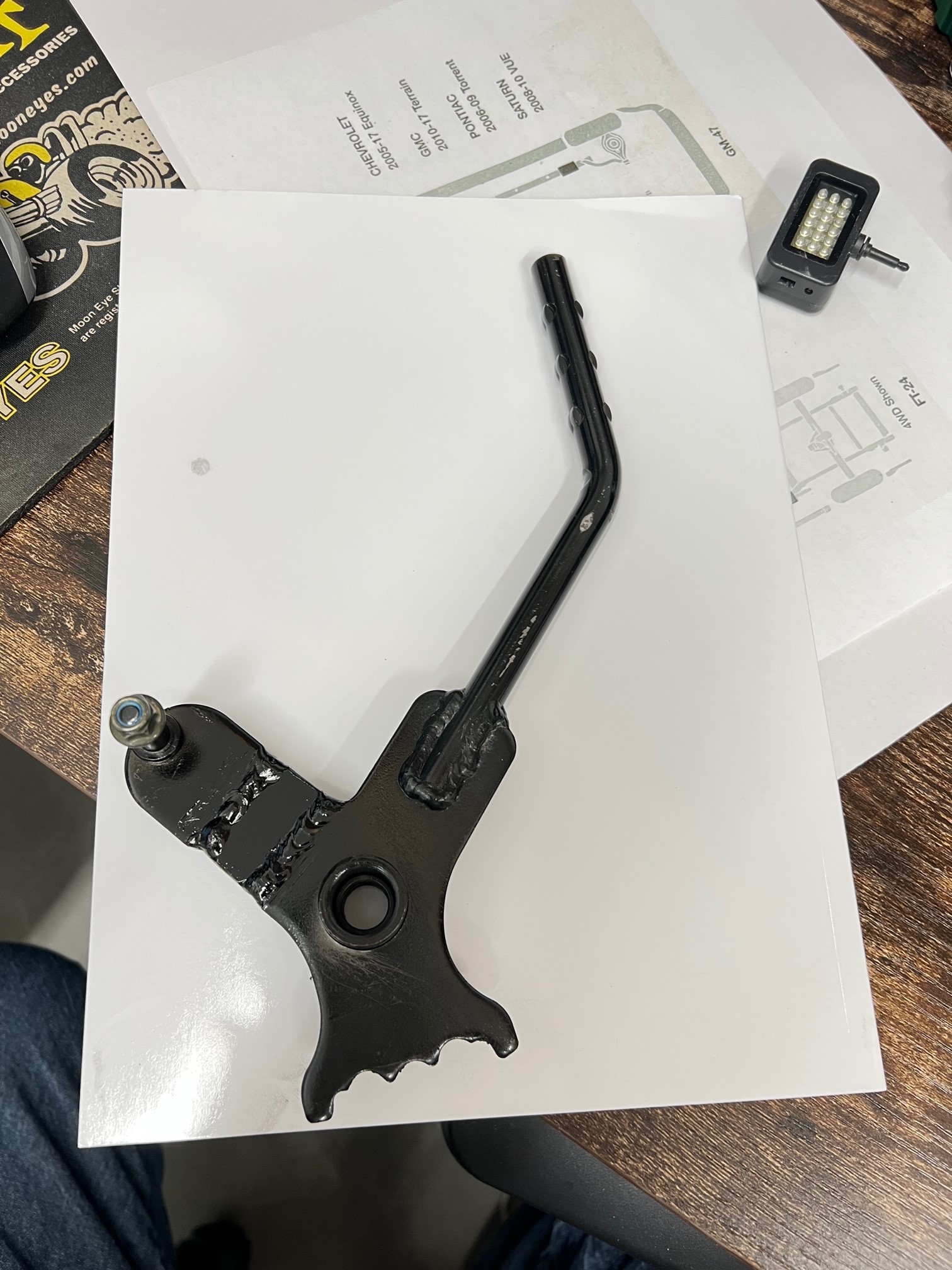
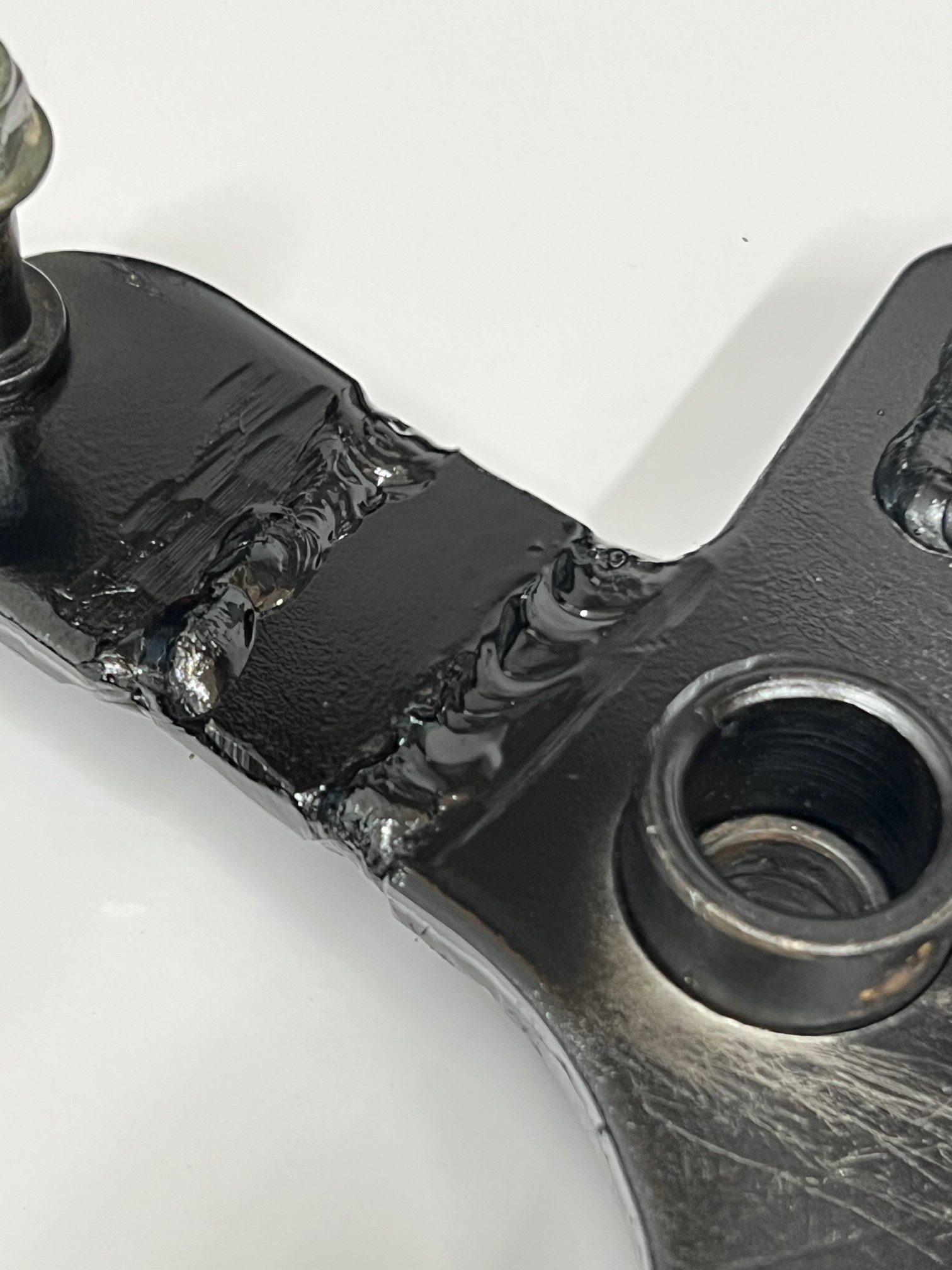
Hello again! I now have a pretty good running Coleman UT400 after a top end rebuild, wet clutch rebuild and a repaired crankcase... ! It plows snow great, but I was also having the jumping out of gear problem, mainly reverse, but a couple times out of forward. I would quickly place it in N and then let the engine idle down and shift again. This worked most of the time. I did some research and found that some have modified the shift linkage. The problem with just adjusting the shift cable is that it really NEEDS more throw, not an adjustment. From what I've read and viewed on the Internet, the linkage arm needs to be about 3/4" longer to gain more throw in both directions. On YouTube, the guy had to remove the shift linkage hole trim and notch the side of the dash to get the shift linkage off the pivot pin. BUT this is NOT necessary. When the "E" clip has been removed and you fish it out of the firewall somewhere, the shift lever is now loose. I had to pop the top of the shift knob off, remove the retaining screw and then heat the lower portion of the knob to get it to come off the lever. Once you have the shift lever loose, push it towards the right to slide it off the pivot shaft. But it won't come off just yet. Use a small pry bar/screw driver and slide the nylon flanged bushing out of the left side of the lever. This lets the lever slide off and get into a "loose" condition and it will twist and come right off without removing the dash trim, that could be a bugger to get back on correctly. Once the lever is off, press out the other bushing so when you're welding on the linkage arm, you don't melt the bushing. I found a piece of scrap metal the same thickness as the lever arm, just over 1/8" thick, close to 3/16". I cut my arm and beveled the edges for better welding. I added a piece just over 5/8" long and kept about a 1/16" gap between the arm and the new piece. Once welded on bother ends, it adds up to just about 3/4" or so. I reinstalled the lever after painting it and did an adjustment on the cable. By the way, it's easier to remove the cable from the bracket on the frame. This gives you more clearance to maneuver in that area with your hands. ALSO, you will need to get a 12" adjustable wrench and slide it over the cable mounting bracket and tweak, to the front, the steel so the cable is pointed upward a bit to now realign with the new longer shift arm lever. There's more than enough metal for the tweak and it will line up perfectly. I now bottom out the shifter on the transmission BEFORE I run out of throw on the shifter... I've tested it just a bit so far and it shifts much better with the longer throw. One of the Coleman authorized repair facilities said that he worked with Coleman to get a new part that's longer by 3/4". He's modified a few and it works perfectly for him. Just doing the cable will just short you on the other end. Here's some pictures of my modified shift lever etc.
3 points
-
I have come to the conclusion @Joe Toup must be one of the very best, most helpful members here!!! He has been tireless sharing his knowledge and expertise helping me solve a problem. I am sure I'm near a good solution thanks to Joe!!👍👍👍3 points
-
There are actually 5 disc brakes on these machines. 1 for each wheel and 1 on the rear driveshaft for the parking brake. I've read several complaints of the parking brake one being too tight from the factory so I would check the cable and make sure there's a little slack when the parking brake is released. If that is good I would jack up each corner Individually and spin the wheel to listen for noise and feel for dragging. That should help pinpoint where the issue is.3 points
-
anybody else getting spam /fraud private messages on here besides me? How do I report it? He calls himself Maria .under ORANGE 15 name.. wants to hook up in UTVs .. con artist in Pakistan probably.. Cant ADMIN block this crap ? geesh3 points
-
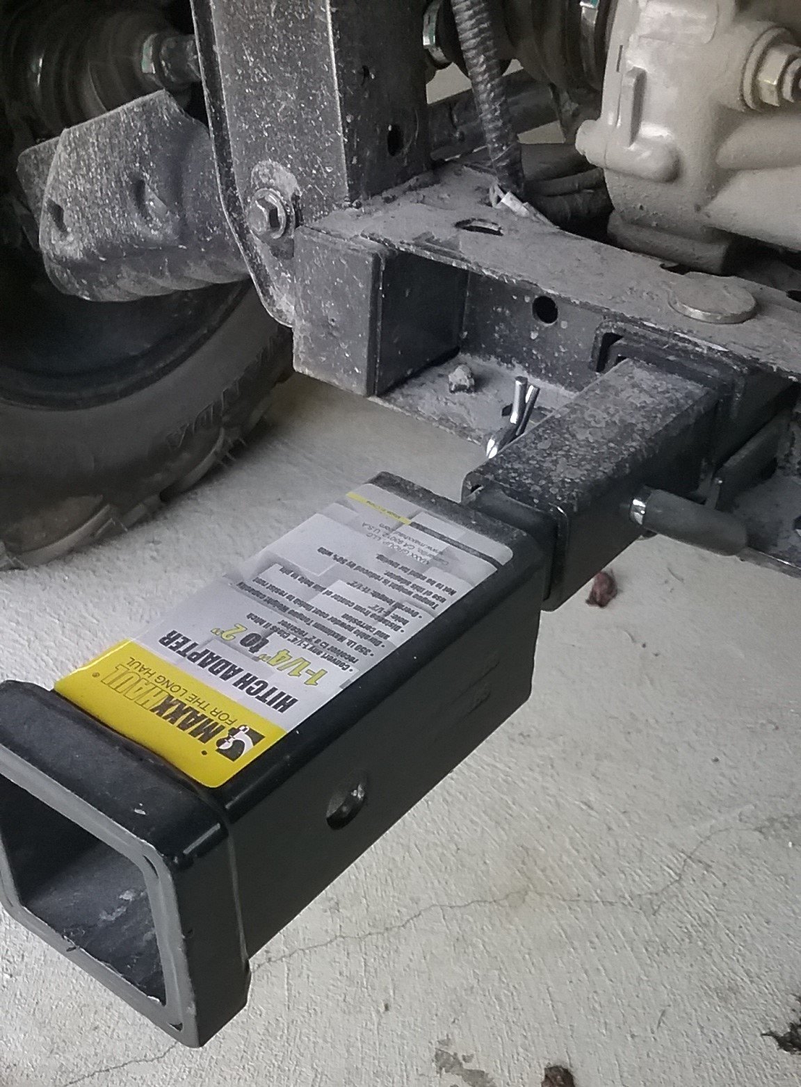
I bought a 2" adapter tube from Amazon and now I just slide my Reese hitch into the adapter.
3 points
-
I'd go for the STINGRAY over any UTV too, but if you can't afford that, I'd run with a CF Moto Z10. They aren't out yet, but for the price and what you will get, the Z10 will be worth waiting for. And the price for the base unit is only $19,999.99. That's amazing!!!2 points
-
I haven't had any service done there, just bought some parts for my Hisun 400 "Menard's Special." Rural King in Circleville, OH. I imagine that if they have parts any RK would.2 points
-
Yep and I bought it for $3000. You will notice that I added a bunch of crash bars on the front, that is cuz I ripped all the fenders of crashing through brush. I made my own fenders out of 3/16 polycarbonate, fit to the frame and no more problems.2 points
-
Congrats!!!!2 points
-
Alien10 I didn't think any disrespect was implied or intended. I really didn't get offended in any way, shape, fashion or form. I REALLY did appreciate the education on the workings of the compression tester. And truly never thought about how it worked. And as a man that knows it all (joke intended), I didn't read the directions. Or didn't receive any. I've had this for 5 years. And either the directions never came with it or walked away. And if I've offended anyone with the blonde comment, I truly apologize. Didn't mean to. It's just a running joke between me and my wife. Anyway, all good. Thanks again.2 points
-
Look for tiny bubbles in the coolant recovery bottle while running and normal temp or hot. Mine never got coolant in the oil but looked like Alka Seltzer in the recovery bottle.2 points
-
Couple of other thoughts... A head gasket can fail to the oil passages, to the coolant system, or to the outside air. Are you getting excessive crank case blow by? Is there any external compression leakage? Are you getting combustion gases in the coolant system? Cap off coolant system shouldn't be expelling gases or pressure. Has the coolant level dropped or increased? Does the coolant appear to be contaminated in any way? (Oily, brownish tinge etc.) Just a few things that came to mind. Good luck.2 points
-
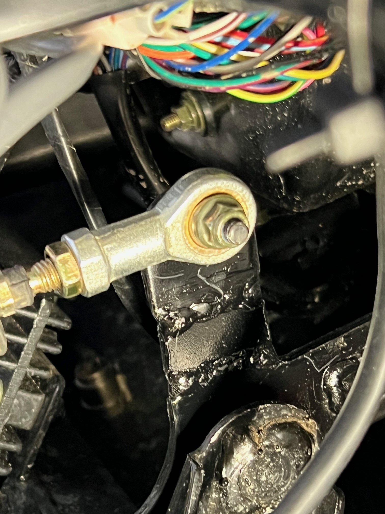
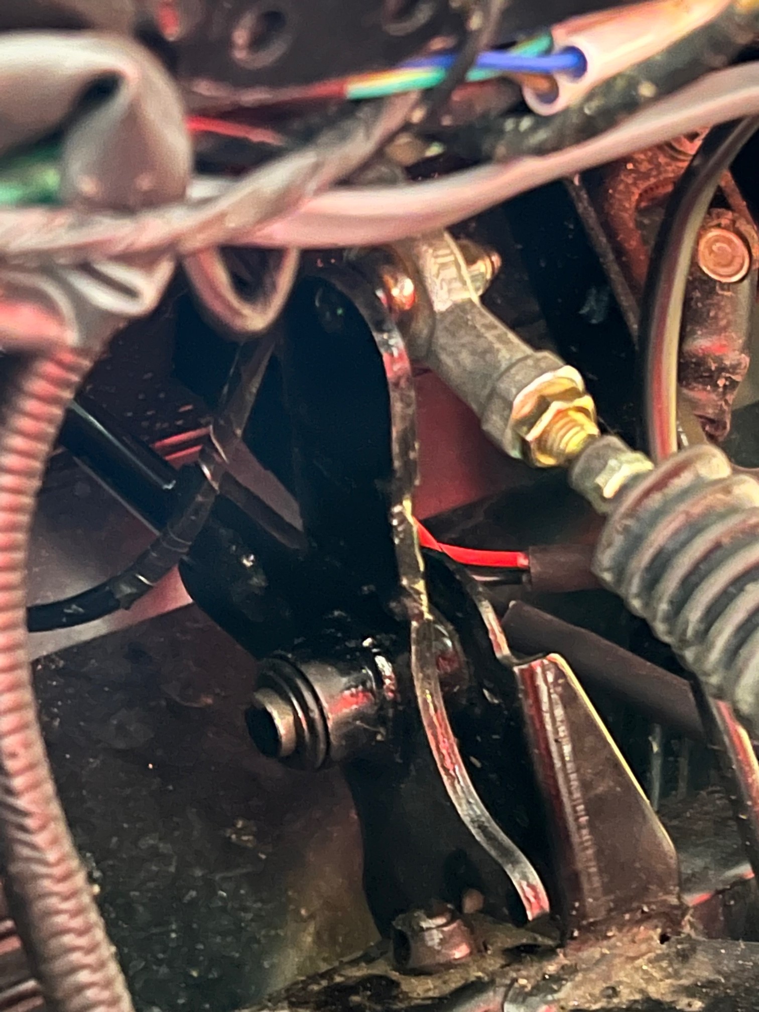
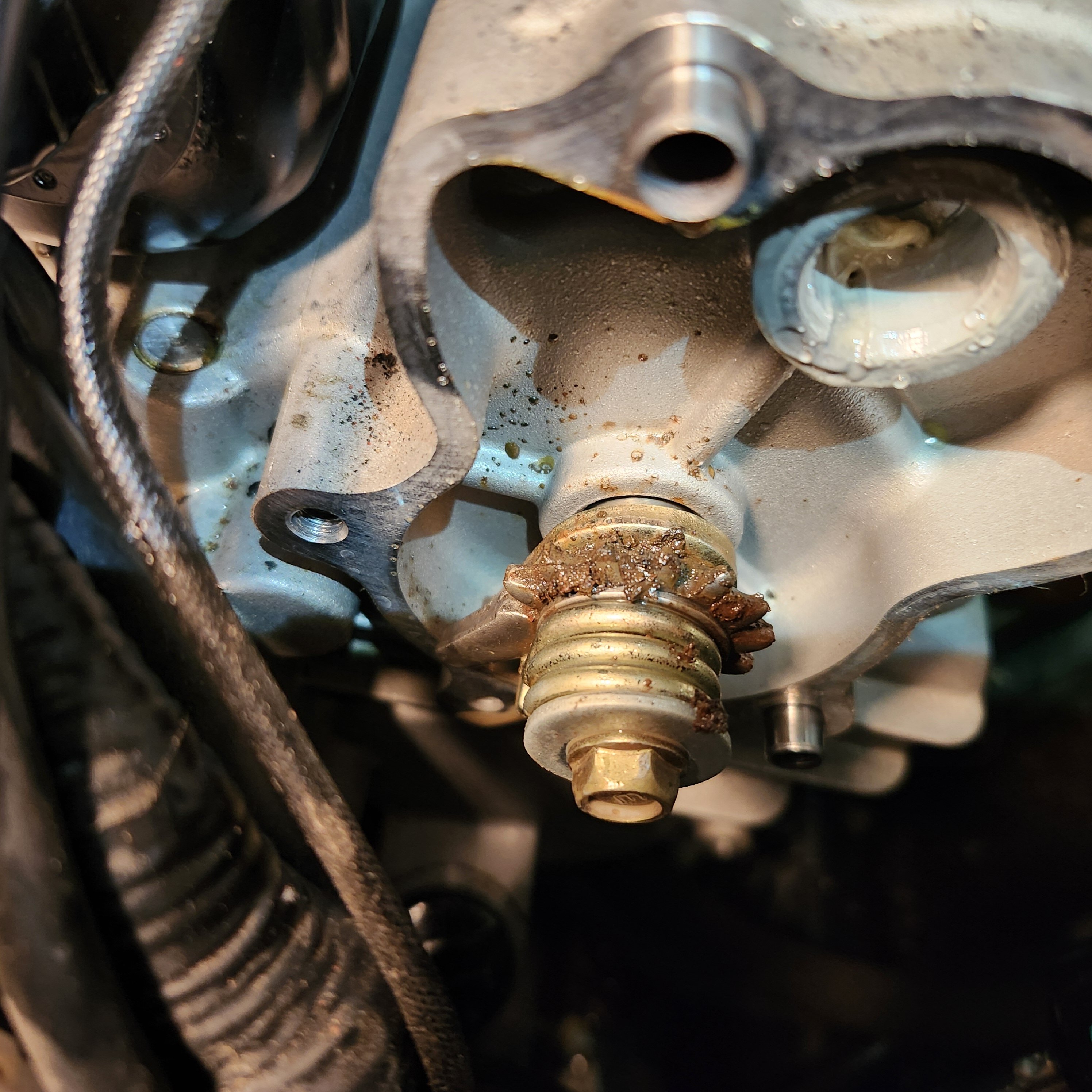
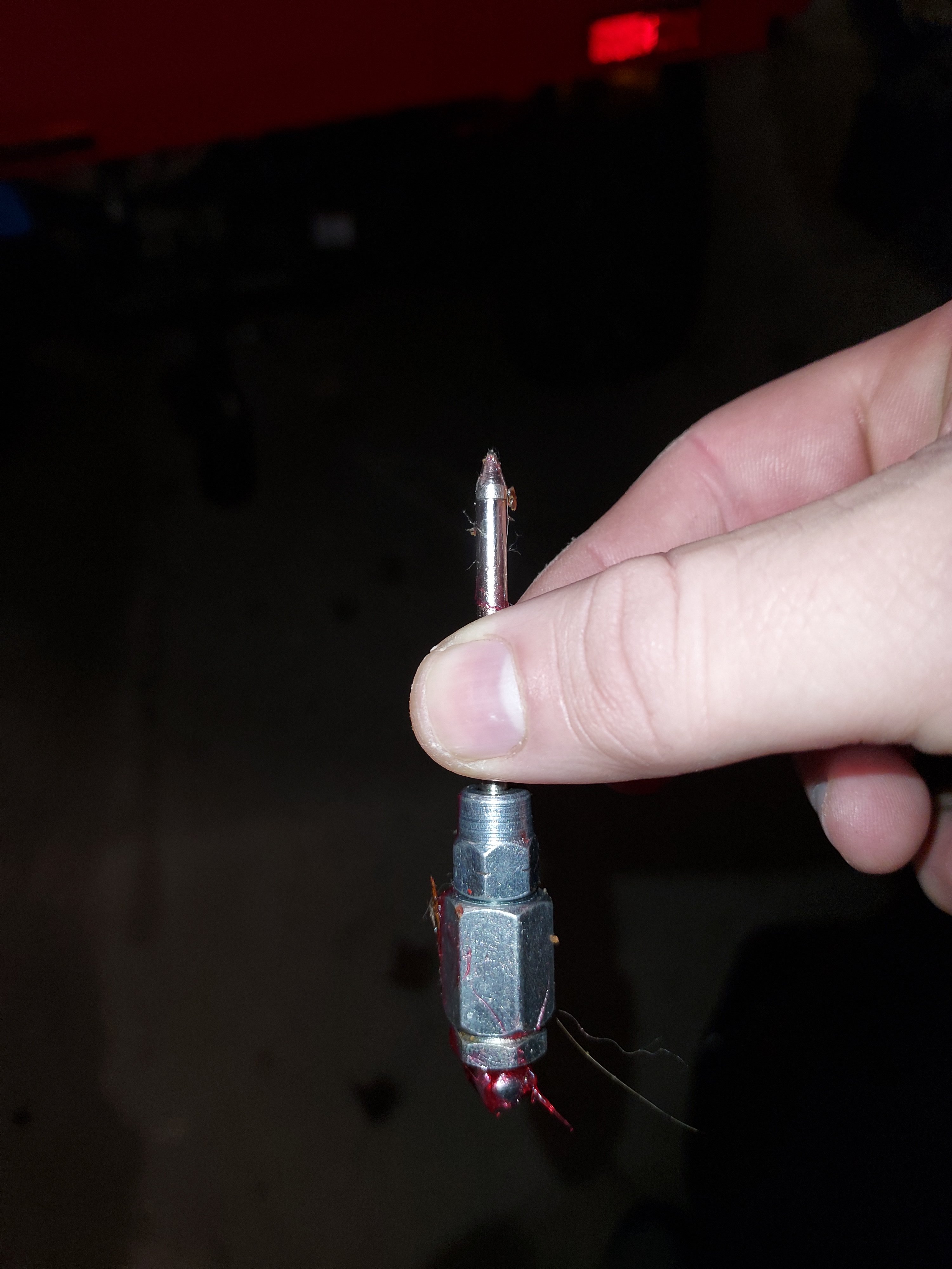
Good news! Its fixed! Thanks Greg and others for all the comments. Really appreciate it. No matter what I tried, I was not able to adjust the shift rod to enable it to cycle thru all the gears. I removed the shift rod and opened the gear fan case. The issue turned out to be the fan gears being corroded. The pic shows the corrosion but it is hard to see how bad the teeth were. I was able to get it fixed by replacing the gear fan and then adjusting the shift rod linkage. This is a walkthru for replacing it. www.youtube.com/watch?v=FABLVRLNHtY Its now shifting better then it did when I first got it.
2 points
-
7 month Update... I've been cutting trails through my woods over the last month or so. The trails are kind of rough and tight, go up and down hills and through mud and swamps, ravines etc. I have to say that my 2021 Axis 500 is really fun to ride. It just jeep crawls over and through everything in 4wd low though I can use it in 2 wd high is more fun to just crawl through everything. Up to riding on my own trails its been on some fairly wide state trails, two tracks and dirt roads. It's pretty fun riding on tight rough and steep trails. I am impressed how well it does. Also been using it to haul stuff around the property like building supplies for my deer blinds, seed, fertilizer for my food plots. Not to mention hauling the deer back to the cabin. .It's a work horse.2 points
-
So I took the leap and did the LiPo4 conversion. I purchased 2 Ogrphy 48v 100ah off Amazon when they were on sale @ $789 ea. All I can say is WOW, the difference is amazing. First is the obvious weight difference. Two 88lb batts vs 8 discover batteries which I think are 65lb each. It actually feels like I have power steering there is so much less weight on the front end. Second is the performance. With the old Discover ones I could only drive around in M at speeds from 5-10 mph for 14 miles before the low voltage code started flashing. One time I wasn't sure I was going to make it back to the house before it shut down. I just got back from a test drive. Both batts were at 95%. I traveled almost 20 miles in H range at or near top speed the entire trip. After arriving home one battery was at 63% and the other 68% so I roughly used 30% although the mfg. recommends not taking them below 20% for longevity. The torque it has now is almost too much. If your driving along at 15 or 20 mph. and you hit a bump, just a little extra pressure on the pedal will snap your head back. It held speed going up modest hills which even when new the vehicle wouldn't do. The battery management system is really great as well. Bluetooth connectivity to your phone. You can monitor each battery for voltage, amperage, temp, and wattage consumed. You can switch either battery on and off even while under motion. It actually drives a little smoother with only one battery on because the torque is a little lower. The BMS has overcharge prevention as well as low temp cutoff to prevent damage. You can also switch batteries on and off while charging. I'm not sure why one battery is being used a little more over the other. I just figure it's slight differences in internal resistances. I may contact the mfg about it at some point and see what they say. Everything worked just the same as with the old dry cells, even the temp. gauge on the dash. I'm not sure exactly were the sensor is so I was surprised when it started ticking up. The dash voltmeter is an unknown what it will show when I get near full discharge, but I suspect due to the nature of Lithium batteries, it will just stay on full until until near the end then drop quickly. My only issue is with the Delta-Q charger. I changed the charge algorithm to 386 which was the closest to what the mfg recommended (57.6 +- .8v) When the batts reach full charge the BMS stops all current flow. This causes the charger to flash yellow and show error code 013 which is battery is no longer accepting charge which is exactly what is happening. My only concern is what if any effect this will have on the charger. I can hear a relay clicking in and out as it continues to try to send a charge to the batts. Does anyone know if this will cause harm to the IC1200? I worry about leaving the charger plugged in overnight because the batts will be fully charged before I can get out there to unplug it in the morning. The only real issue I had with the installation was the physical size of the new batteries. They are much larger so they did not fit in the tray the way the old batteries did. I had to remove the trays and build a wooden ones and use ratchet straps to hold them in place. That will work for now, but I will need to figure out a better arrangement in the future. I am extremely pleased with how this all went and knowing I will get many more years of life out of the E1. I highly recommend this upgrade if you are considering it. The only unknown is will the batteries keep working without issue. They do have a 5 year mfg warranty, but since they come from China (as most things) who knows if they will be around then, but it wouldn't kill me to have to buy a replacement at some point at that price.2 points
-
Lol, like you need more rain in the swamp 🤣2 points
-
I work on a ship that travels between Houston, Southern Lousiana, and Florida...miserable all summer. I dont know how you guys manage it. I never seem to find the right balance between staying hydrated and peeing constantly. I have worked asphalt barges in Lousiana in the summer too. 300 degree cargo means the temperatures on deck are even hotter since it radiates through the steel. Much nicer at home in Maine the other half of the year.2 points
-
I guess it's whatever you are used to. Personally, I don't do well with humidity above 70%, like Alien10 says. I rarely leave the a/c in those conditions.2 points
-
I fixed it -- evidentley when I checked the oil one of the times, I unplugged a green wire -- changed the oil today, noticed the unplugged wire, and now the issue is resolved...2 points
-
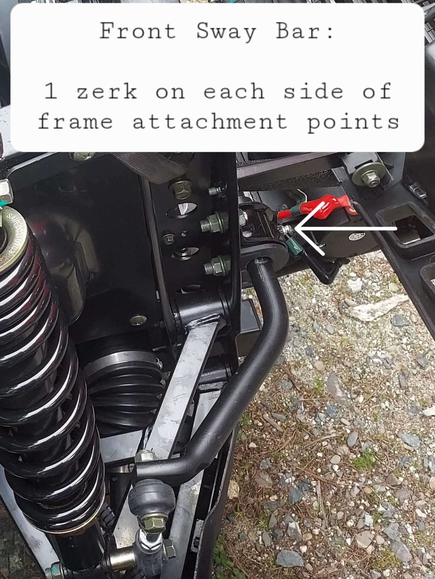
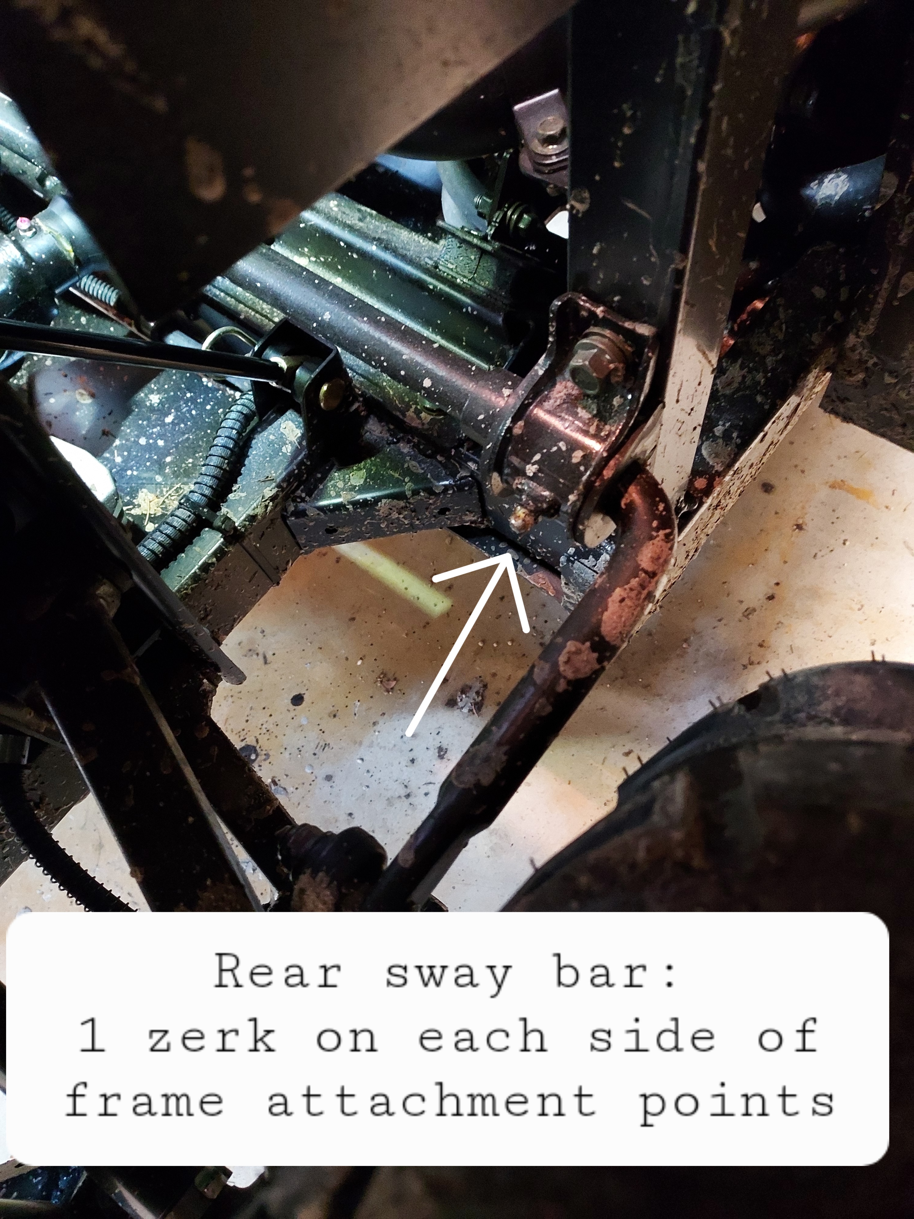
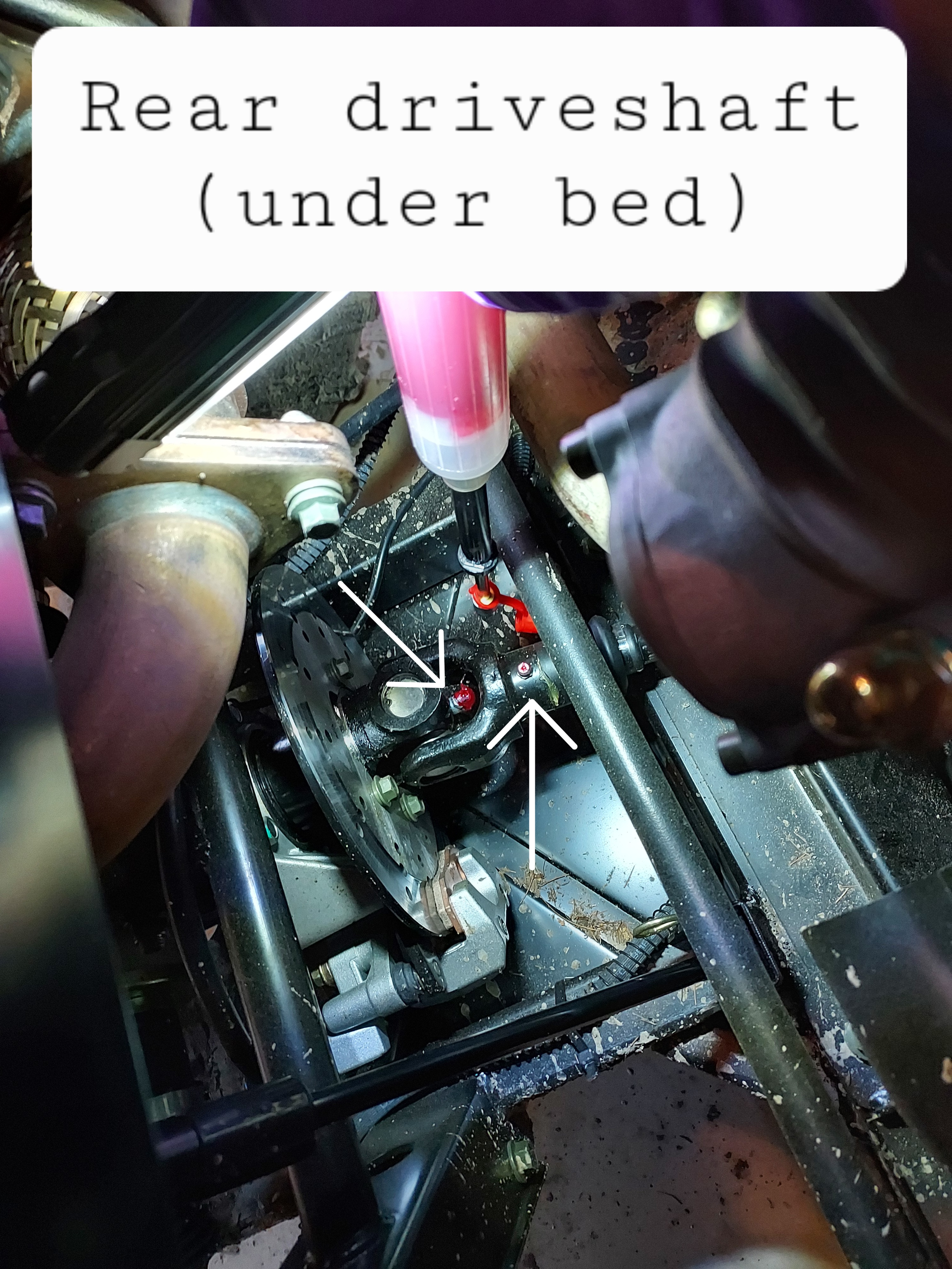
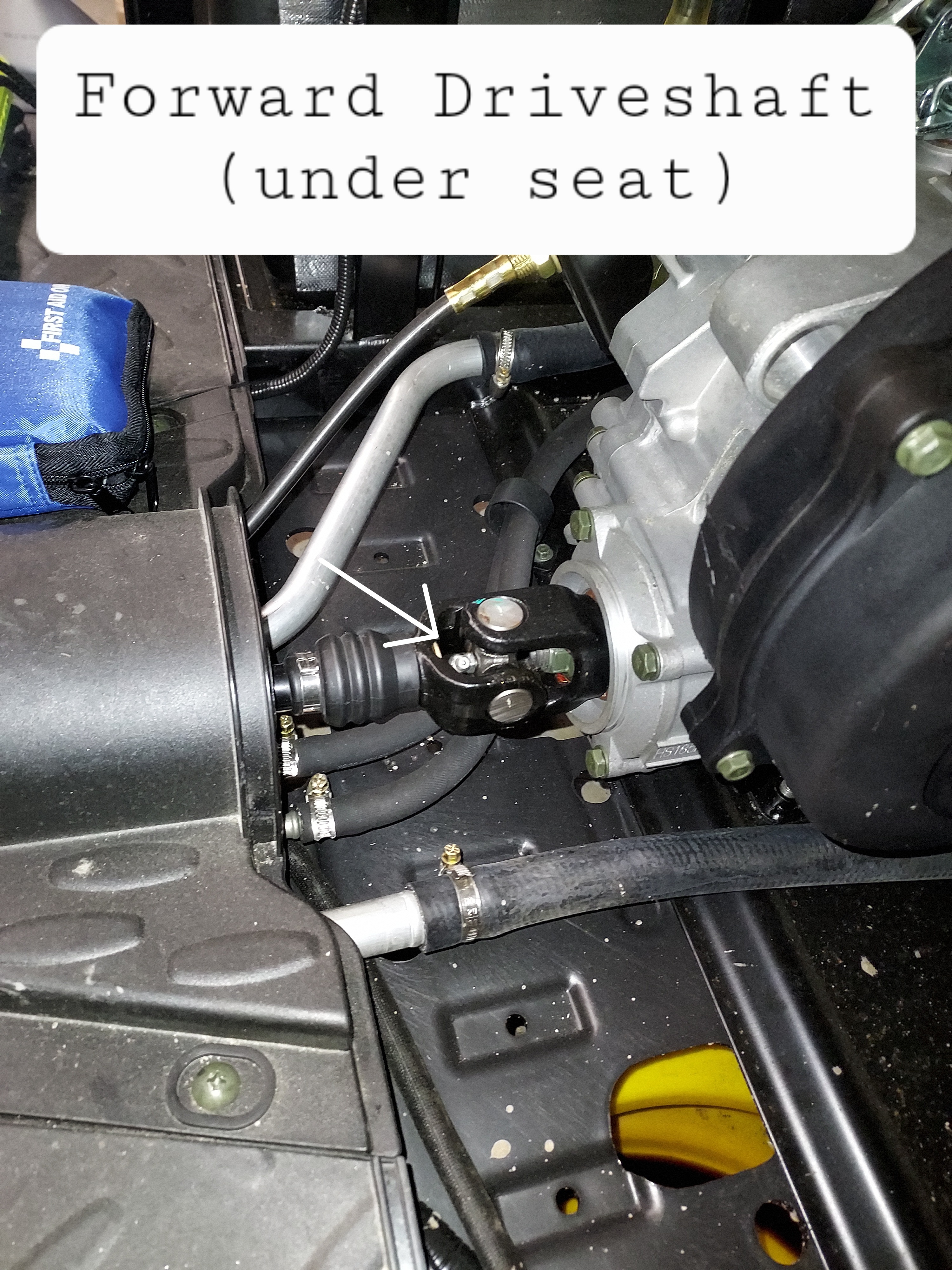
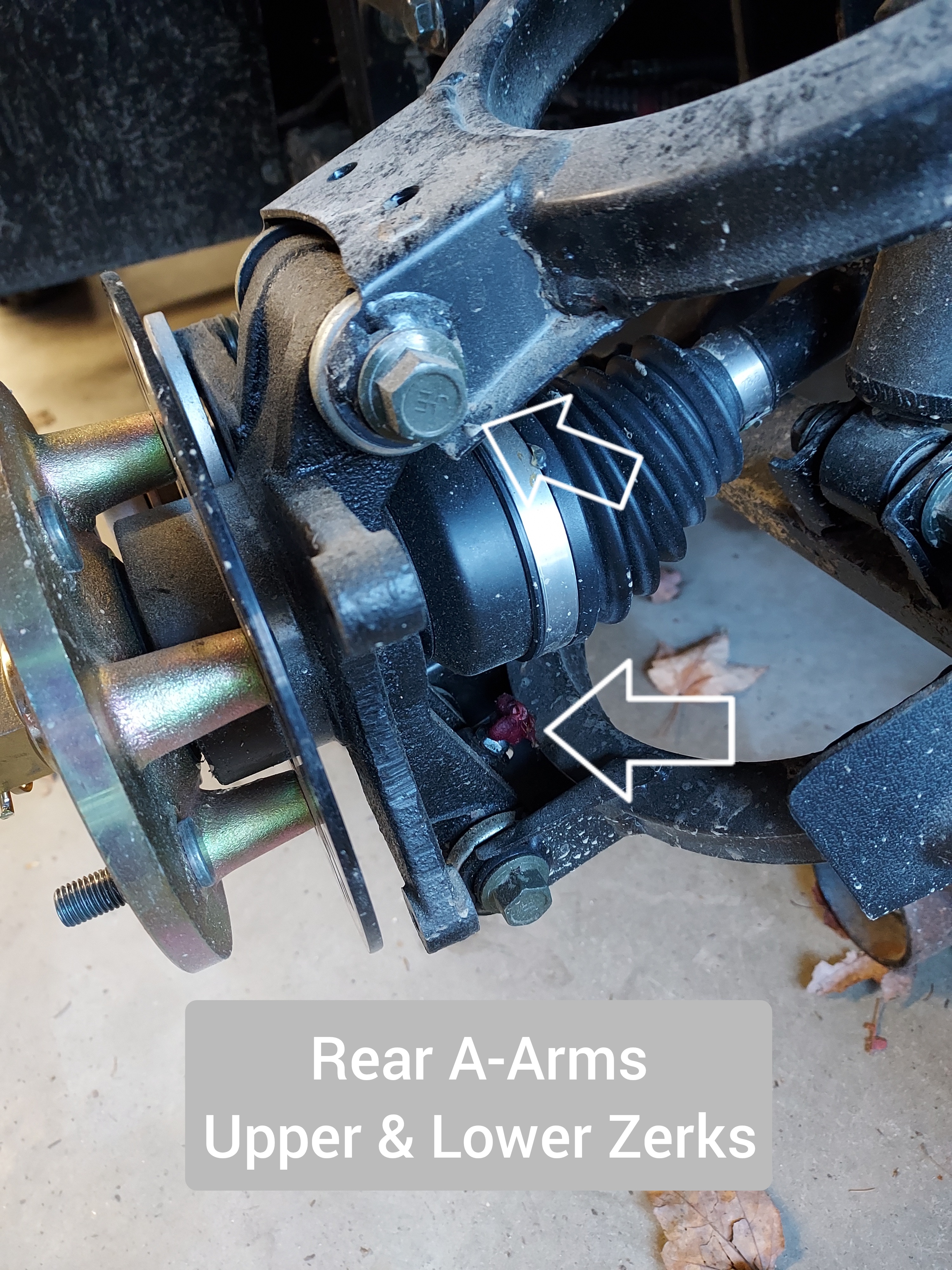
I've seen a number of requests for the location of all the grease points on these machines, and there is no definitive list in the manual. This covers the UT400, but other Coleman/Hisun models should be similar. Tools: First to grease your machine you need a grease gun and some NLGI#2 grease. You will find it helpful to buy a needle attachment as pictured here, due to poor clearance on some of the U-joints. The rest of the zerks use the standard attachment. Technique: Wipe any dirt/grease off the zerk before greasing to prevent pushing gunk inside and causing excess wear. Push the grease gun on the zerk at a straight angle and give it a few pumps. You will hear an oozing noise or sea grease coming out from the outside of the greased area when you've put enough grease in, a few pumps should be plenty. If it's just oozing around the zerk you either don't have a good seat with the gun, or the zerk may be rusted and the check ball frozen. Try seating it again and regrease. Wipe up any excess grease when youre done to prevent making a mess. Greasepoints: Rear A-Arms are greasable with the wheels on from the rear, I took the picture with the wheel off for easier visibility That's it. All other Hisuns should be substantially similar.
2 points
-
Yes, please see what you can do. Now, ads are popping up on top of posts and I cannot shut them down, so I can't even read certain posts. I click on the X in the corner and the ad changes with an arrow in the opposite corner. I click on the arrow and the previous as appears.2 points
-
happy new year!2 points
-
The main trick is tilting the front end up. Block the rear wheels and jack up the front end at least a foot. A convenient ditch works well also.....rear wheels in a shallow ditch. The head bleeder screw should be opened. With the engine NOT running, almost fill the radiator (leave some air to avoid a mess) and burp (squeeze the lower hose line before the metal tube at the engine base passenger side floor area). Watch the radiator and the the bleeder. With the radiator "higher" than the head bleeder, the air should be bled and coolant dribble out. Close the bleeder and refill radiator (your clue you displaced the air with coolant) and start the engine. Burp more while running and if you get the circulation going the hoses will warm up. More bubbles should surface at the radiator filler neck. Shut off engine. Open bleeder and release any air in the head. The puke jug needs to be filled about an inch above the full cold line. Use a shop towel as a "seal"and use an air nozzle to SLIGHTLY pressurize the puke tank removing the air from the tubing line to the radiator neck. Then the radiator starts to overflow, a third hand can install the radiator cap. Run the engine and determine the head and hoses are at the close to the same temperature (as in warming up) through out the system. IR temp gun....fairly cheap now....can get real numbers. Scan the radiator, hoses, cylinder and head.....if all close you are done. Recheck fluids when done riding. Recheck the bleeder and top off the puke jug as required.2 points
-
From the look of the picture on the post, I can think of a couple things2 points
-
I finally found a service manual in stock and was able to make the adjustments per the specs!2 points
-
The P.S. has me thinking......you mention "Fuel mist" out of the valve rocker cover. All you should is basically NOTHING at crank speed. Any vapors blown out are from blow by (past the rings) into the crankcase. IF you are OVER FUELING and wetting down the cylinder walls (that is, washing off the oil coating) you will have blow by. Oil coating helps seal the rings. That is why an engine that has set (dried out) and low compression is given a shot of WD-40 or any light oil to seal the rings. This leads to the next thought.....If over fueling, the raw gas will "drain" into the crankcase and dilute the motor oil. Check motor oil level.....too high?....too thin?.....wipe on tissue and sniff the oil....Gassy smell?....will light off with a burn test (soak up some oil on a paper towel and see how fast it starts to burn). Oil basically won't. Diesel will start slowly but take off. Gassy oil....if you value the hair on body parts...hold at a distance with long needle pliers!!!! Gassy diluted motor oil will add to the fuel/air mixture via the breather tube. Similar to a turbo seal failure on a diesel......RUNAWAY even after the injector pump shut down...very bad ending! Drain oil and replace filter....won't get it all (always some oil remains that cannot drain) but will dilute the gas. BONUS: Pulling the vent tube will clean up a mystery RICH run be it carb or FI (everything is correct BUT) after the motor warms up and cooks off the gasoline----sorta like an EGR Evap system. Slop fuel never lights off or barely runs depending on the degree of "slop". You state pulling the injector, the engine runs until it runs out of fuel. ARE you leaving the injector hole OPEN. This will allow lots of fresh air into the cylinder and will light off a rich mixture and then die because no more fuel is injected. ASSUME the ECM is sending the correct pulse width to the injector for now. Injector can hang and "piss" instead of spray. The key is the 14.7/1 air fuel mixture. Too RICH.....runs heavy and then dies at idle. May start to run, but as the leftover UNburned charge gets richer-----labors-----pukes. Too Lean......no start....fuel is there but cannot lite off.....then as it builds up, you get a pop only to be to lean again.....repeats the cycle.....THIS IS HELL ON THE STARTER AND REDUCTION GEARS. This also load the oil with gasoline (unburned). Again the fuel correct, look for a restriction in the air intake (not enough air).....common causes....CRITTERS...mouse house....full of acorns....rag pulled in for a nest, and so on. EASY TEST: Remove the air intake plumbing at the throttle body. Plenty of air now. If runs, check out the air box/plumbing. IF NO RUN....next section. Too much fuel: Time to test the ECM/injector system. ANY BAD input signal to the ECM will make the fuel delivery too much or too little. Pull spark plug. Read the insulator tip color. Just right is a light TAN color. Very WHITE...blistered LEAN. RICH has a BLACK, SOOTY, shiny black/wet black (carbon is fuel soaked). If really black, they might fire outside to the engine block BUT "blowout" under compression even at idle. If not too bad, they might run at idle but when sputter and die when a heavy demand on the ignition system (acceleration) is applied....drop in a new plug for testing to just to reduce the possible list of problems. Pull the connector to the fuel pump (under the pass seat). This is the fuel pump power (from ECM) and fuel level signal. No guessing if you found the right fuse/relay. This will stop the fuel delivery (40 PSI) to injector. Injector will still get pulses. You will shoot a short burst of starter fluid into the air box (plumbing reattached and filter OK). The motor should lite off and run until it is out of fuel. Repeat. Repeat. If works every time, give a double burst when running to "sustain" the run. Repeat. If this works, you have the ECM/input signals to ponder. This gets deep for most. Coolant temp sensor....open circuit RICH. Thinks it is at the SOUTH POLE -40 C. Like a choke for carb. Throttle position sensor.....wrong fuel mix to match the air thru the butterfly valve. MAP sensor/ambient air temp....measures engine load....wrong signal rich and lean. O2 sensor....signal to tell if RICH or LEAN. Has heater circuit to get it up to operating temp. Heaters open (toaster that does not toast). Throw in smashed wires, critters that live the taste of plastic insulation on wires, stick run thru harness, heater shorted to SHARP edged heat shield above the exhaust. More common failures are the MAP/IAT (intake air parameters) and O2 sensor. You got a lot of checks to get down to where the problem is. BTW, the ECM is a DELPHI MT05 small engine unit capable of a twin (2 inputs for the two cylinders individual O2 sensors). Check out web page for specs, pin outs for both the Grey and Black connector (PDF format)....magnitudes better than the "manual" supplied when first built. Only covers the electrical engine management with a generic diagram of the analog input(s) and the outputs like fuel pump, ign coil, etc CHOW.2 points
-
Hey now, that ain't right 🥴2 points
-
Thanks but think I found the critter , the cam pressure relief spring had broken had to remove the head again to make sure nothing got crushed , but found everything installed new spring put back together , but made sure that the timing marks were where they were supposed to be , adjusted valve springs and it started right up, ran for a few seconds and I believe some garbage got into the fuel system , but thats for tomorrow problem solving !! ROFL thank's for sharing2 points
-
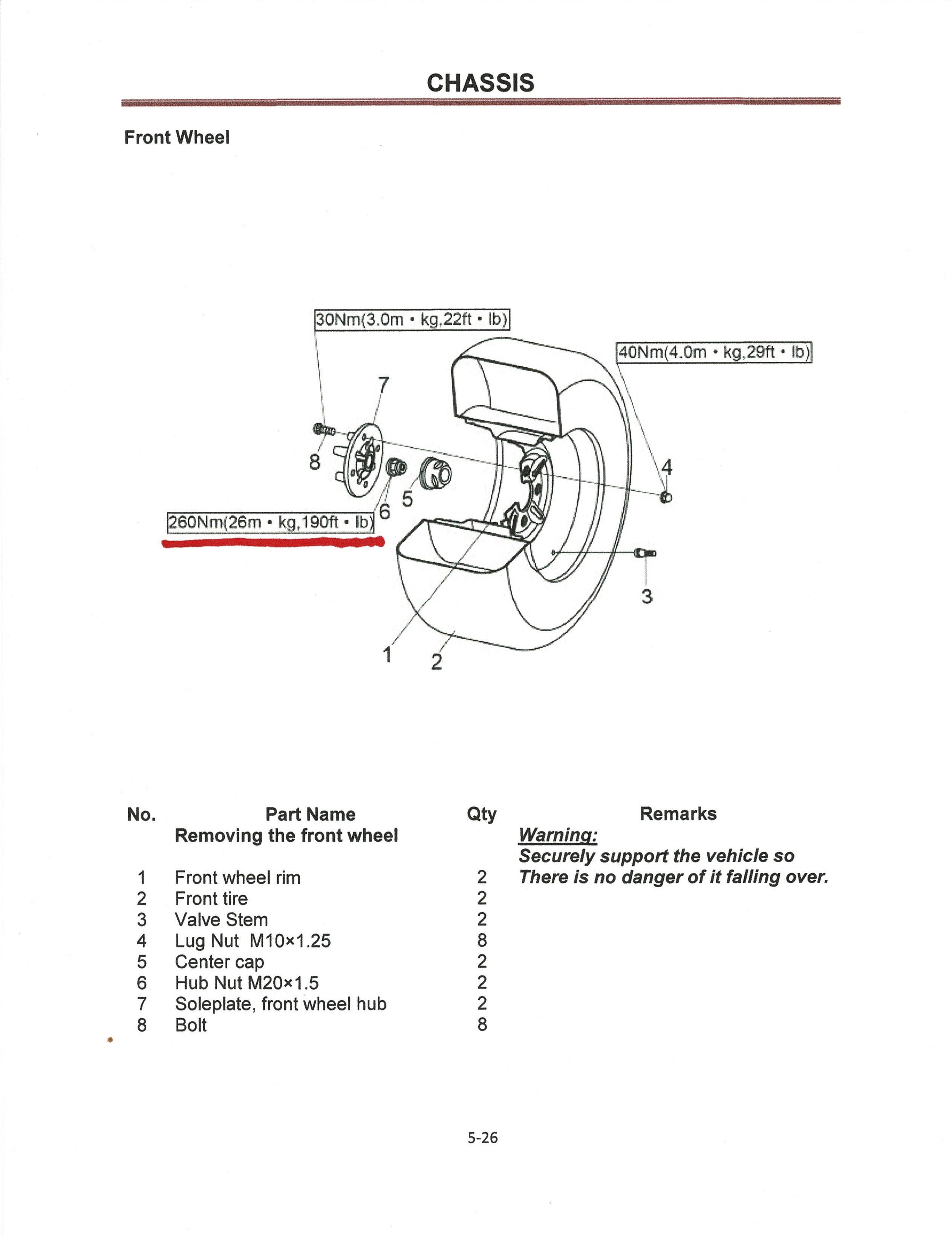
I had Front left brake squeak. Removed wheel to investigate and found hub nut loose. Torqued to specs as close as I could, and that seems to have cured brake squeak problem.
2 points
-
Really hard to work out what happened. My view would be that it was a loose connection, If it was a battery going up, it would have been caused by a gas explosion and at least one of the batteries would have made a fair noise when it went, but if it was a poor connection then heat could have built up, to the point where the plastics melted and caught . Hard to track it down now, but a quick check of whats left of the cables could show up where one was loose. Such a horrible event. There have been other comments on a FB page when a faulty / inconsistent vehicle turned out to be a poor connection on a battery terminal. Personally I would swap the horrid 10mm headed painted battery bolts for m8x 20 Stainless screws and washers with single springs. Worth regularly checking their tightness. Another alternative cause could be the 12v battery. I have found one that was totally shot. But its not apparent to the user as the DC to DC runs continuously even when the ign is turned off. In this case a duff 12v battery will simply get hot and over heat, when over heating the electrolyte boils off, when plates touch they can spark and ignite the hydrogen inside the battery. My suggestion to users is to get a multimeter go under the drivers seat, find the 12v battery and (behind the drivers legs) and check the voltage (negative is towards the centre positive towards the side panel). Note the voltage. Hit the big red button. That breaks the 48v circuit. The DC to DC will shut down. Leave it for 10 minutes. Re check the 12v battery. If its well above 12v it should be OK , if not then your battery may need topping up , or replacing. If below 12v then its a replacement, as its way under voltage, and probably has one cell dead.2 points
-
You might have missed a wire connection or something similar. It's not that uncommon to break other stuff while you're working on something. It happens, and you shouldn't worry about it. Just move on, and focus on finding the problem. You need to go over all the wiring that might have been disturbed, or disconnected, while fixing the last issue. It cranks, but have you looked to see if it's got spark? If not, then check the coil2 points
-
Doc IV I’ve been told that running it below 25 mph in high range is harder on the wet clutch, and will cause early failure, running it faster in high range is fine. I don’t know if it’s true, but a friend ran his HIsun 700 in only high range, and burned up his wet clutch in 100 hours. Motor Cycle Doctor says it has to do with a combination of low oil fill, and running it in high range. So far following that advice, mine runs fine. Most of my use is under 25 Mph, When I intend go faster, I put it in high range.2 points
-
Update on my Axis 700. Contacted Lowe’s to explain what happened. Store manager, Fatima, in Mechanicsville VA was awesome. She paid for my gas for the round trip back which was $170 and then doubled it. She then gave me a new 700 with full tank of gas. It ran good yesterday so we’ll see. I told her if any happens again, I will be taking it to the nearest Lowe’s for a full refund and she said she would make sure it was taken care of. The original 700 did start after a trickle charge. Had to be a bad alternator, or loose wiring. These things do happen. I wish I could purchase a more expensive utv, however I lost my job because I refused to take the vaccine, so I’m on a budget. This definitely fits my budget. Great deal when you add my 10% military discount.2 points


This leaderboard is set to New York/GMT-04:00