
Leaderboard

Popular Content
Showing content with the highest reputation since 09/24/2019 in Posts
-
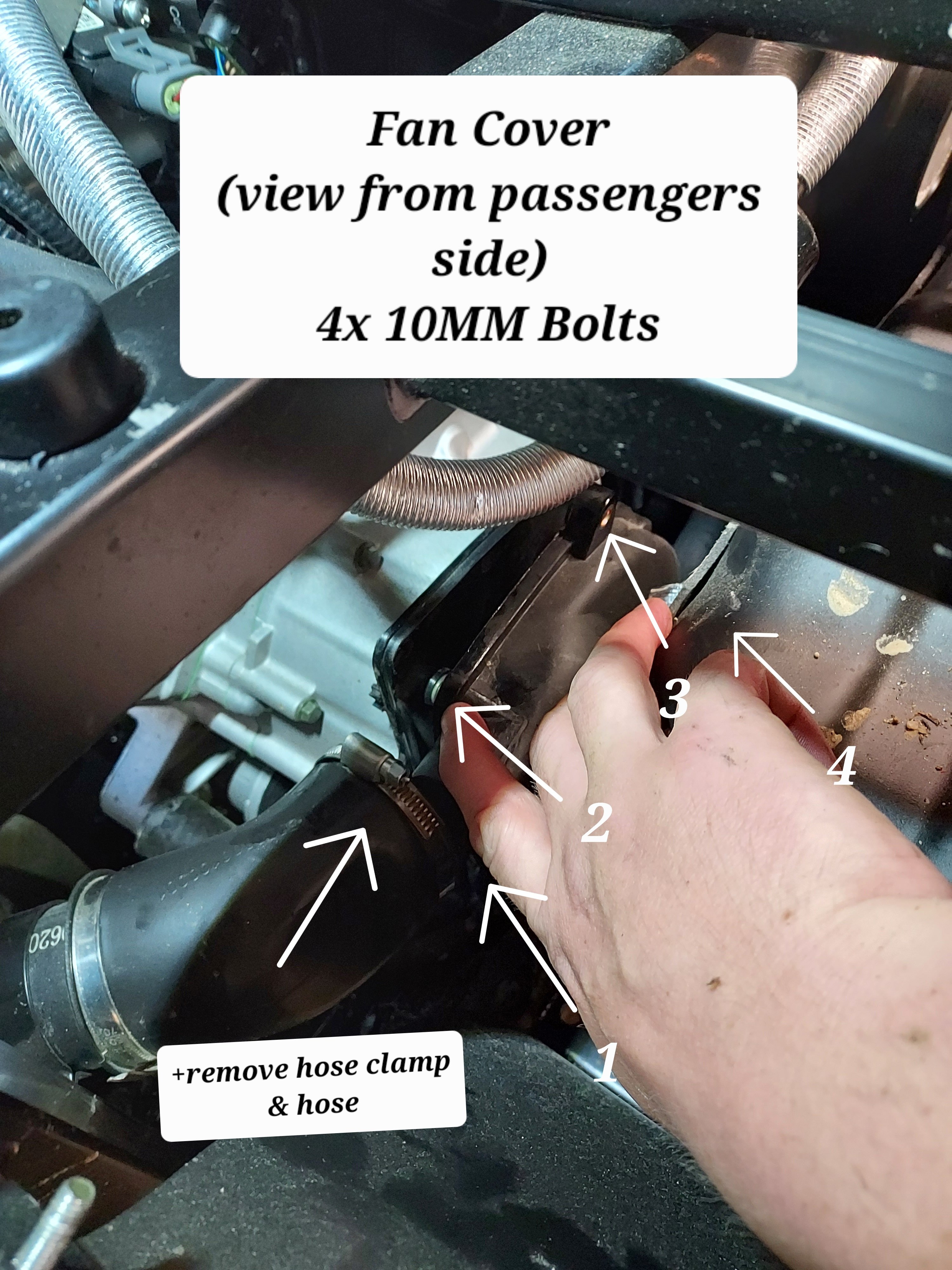
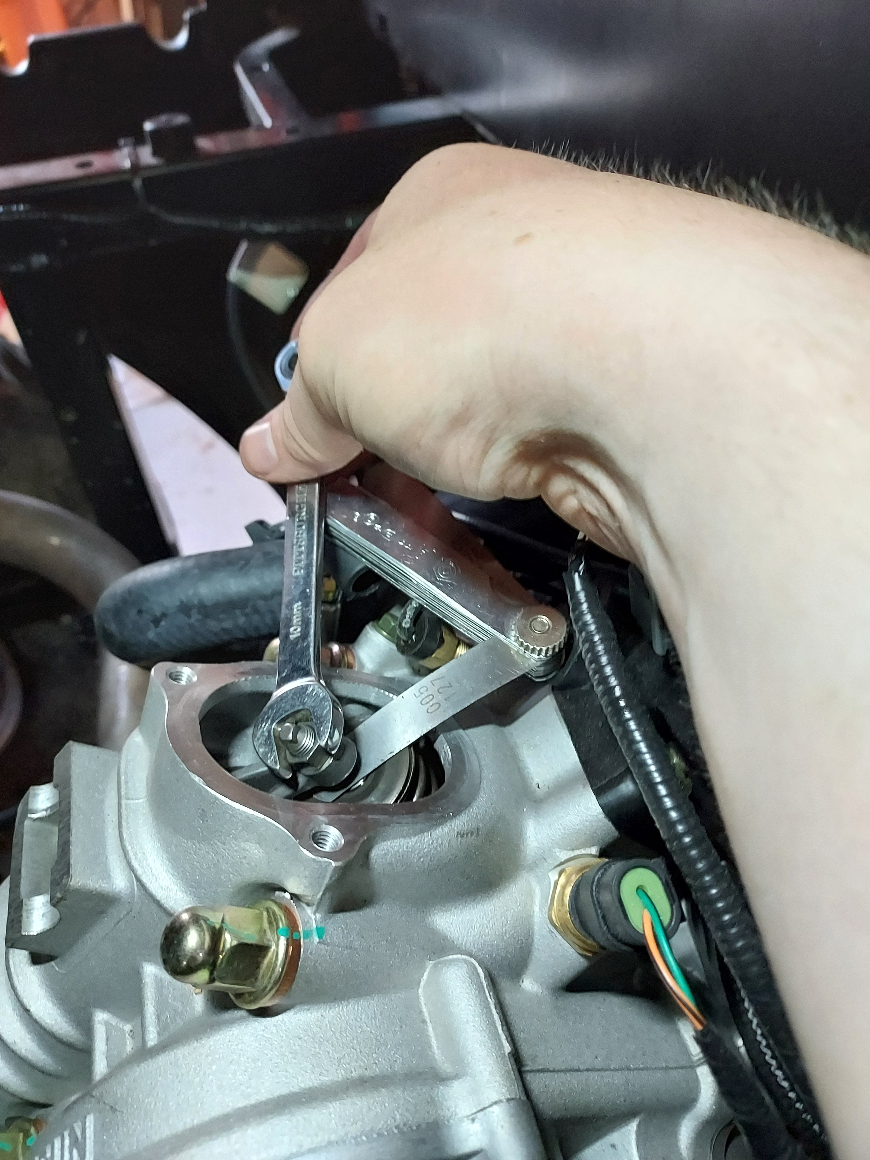
Since I've seen some questions on this I took some pictures and will provide instructions on a valve adjustment for the UT400. This should be the same for the 550's and other various Coleman/Hisun single cylinder models with the cylinder slanted aft. I have seen several people ask of it is really necessary, and read several reports of valves being out of adjustment from the factory. My valves were .004" intake, and .010" exhaust with about 5 hrs on the machine. I've seen different numbers thrown around for factory spec, but I decided to go with 0.005". This is called valve lash. What is is is a gap between the rocker arm and the valve then the camshaft isnt opening the valve. Why does it matter? If it's too large the valve doesn't open all the way, if it's too small the valve dosent close. This can cause valve damage (overheating) as well as loss of engine power (burned fuel is going out exhaust rather than pushing the piston dow). Tools required : 5MM Allen wrench, 10MM box wrench, needle nose pliers, flat feeler gauge set, rags First you need to remove the fan cover on the passenger side. There is a cooling vent hose on the back side, remove the hose clamp and slide it off. From there there are 4x 10mm bolts holding the cover. The forward ones can be accessed from under the seat. Next remove the spark plug from the drivers side. Carefully wiggle the spark plug wire off. Grip it as low as possible and give it a little twisting motion as you pull it off to help free it. Its a tight fit for a socket, but there is a sheet metal wrench in the toolkit that fits it. Unscrew the plug and set it aside. This allows you to spin the motor over freely with no compression to fight. When you reassemble this is a good opportunity to switch to an NGK iridium plug for better performance/less fouling DR8EIX) Next you need to remove the intake and exhaust valve covers. The intake us the forward one. There are 3x 5MM Allen screws to remove. The Exhaust is the rear with 2x 5MM Allen bolts. Both covers have O-Rings instead of gaskets and are reusable. When you remove the rear be careful and use your rags as there will be oil that drips out. Next up we need to spin the motor over to top dead center. Grab each rocker arm and give em a little wiggle up and down. Spin the engine over by grabbing the fan with your other hand. Spin the engine over until both rockers have some wiggle and are loose. Once both rockers are loose slide the feeler gauge in like shown above. Try different feelers as needed to determine your starting spec. You should feel some drag but still be able to move the feeler without too much force. If you need to adjust, use the 10MM wrench to slightly loosen the locknut, then with the correct feeler gauge in place, tighten the top square nut while wiggling the feeler in and out. Once you have it right you need to tighten the 10mm lock nut without moving the square head bolt. Once the lock nut is tight recheck the clearance. That's it, button everything back up and make sure you have it all reassembled before running it again. If you find this helpful give me a thumbs up or comment. If you have any questions or need more help let me know. If there's interest maybe I'll do some more of these
 6 points
 -
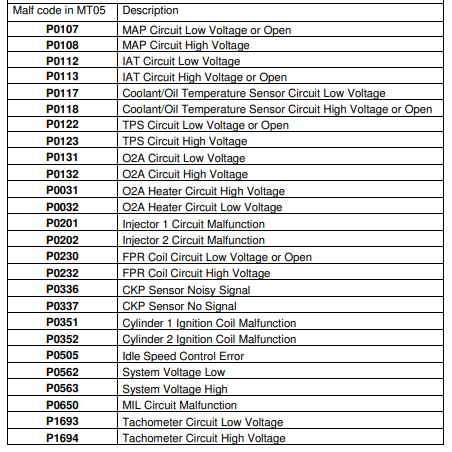
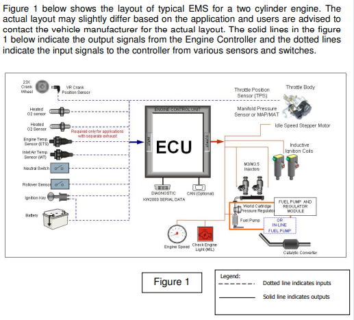
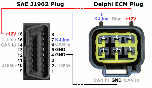
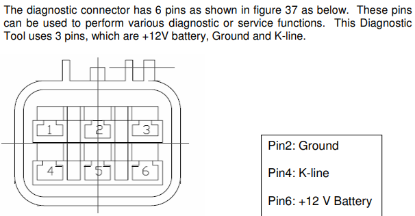
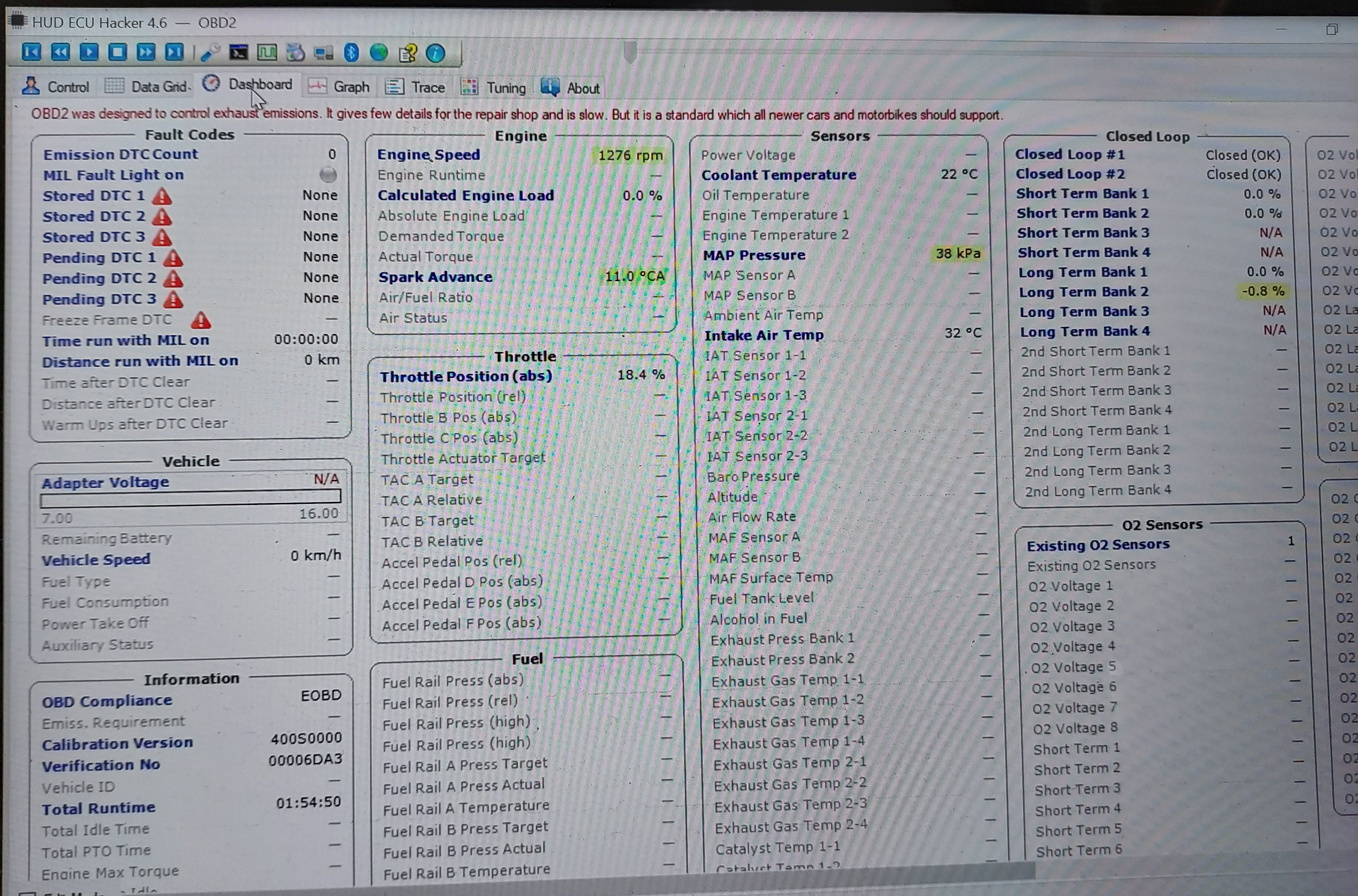
Hey Folks There are not a lot of good sources out there for troubleshooting and diagnosing ECU problems with the Massimo Buck, Bennche Bighorn, Bennche Cowboy, & Cazador machines that use the Delphi MT05 ECU. They are all basically the same with different badging, so I thought I'd share some info that I found during some searches. I was trying to help someone diagnose and repair a hard starting issue. The ignition coil was throwing a 0351 code. I discovered how to read codes without an OBDII code reader. The following procedures should help you check your fault codes and clear them if needed. Fault Code Troubleshooting for Delphi MT05 ECU on the Massimo Buck 400, Bennche Bighorn 400, Bennche Cowboy 400, and Cazador 400 *NOTE: The MT05 ECU is not really OBD 2 compliant. It is much more similar to an OBDI system. The MT05 ECU controls either 1 or 2 cylinder engines commonly found on Massimo, Bennche, and Cazador. Much of the ECU info was found here: https://netcult.ch/elmue/HUD ECU Hacker/Delphi MT05 Manual.pdf Delphi EFI System Design Delphi EFI employs 5 sensors to monitor engine performance. 1. Crankshaft Position Sensor 2. Coolant Temperature Sensor 3. Oxygen Sensor 4. Throttle Position Sensor 5. Manifold Air Pressure/Manifold Air Temperature (MAP/MAT) Sensor Delphi EFI employs the following system components. 1. MT05 Engine Control Unit (ECU) 2. Fuel Pump 3. Multec 3.5 Fuel Injector 4. Idle Speed Control Valve (Idle Stepper Motor) 5. Multec Ignition Coil 6. Fuel Vapor Canister Purge Valve Using the Digital Dashboard to Decipher EFI Trouble Codes In addition to commercially available diagnostic scan tools (Big $$$), you can use the engine warning light of the Siemens dashboard to diagnose most of your EFI problems. The digital dashboard receives signals from the MT05 ECU, and the engine warning light will flash a diagnostic trouble code (DTC) if the ignition key is switched on/off for three cycles. When you turn on the ignition, the engine warning light will illuminate, which indicates the EFI system is operational. After the engine is started, the engine warning light will extinguish if the EFI system is working properly. However, if the engine warning light remains illuminated, it indicates the EFI system is not working properly, and there is a system component failure. Deciphering Diagnostic Trouble Codes To read the diagnostic trouble code (DTC), open and close the ignition key three times in rapid succession, as follows: open/close—open/close—open. At this point the engine warning light will flash a DTC which indicates the fault in the EFI system. Refer to the attached fault code table to identify the corresponding problem. The engine warning light will emit a sequence of flashing lights. If the light flashes 10 times, the translated number is 0. If the light flashes one time, the translated number is 1, et cetera. For example, if the MAP/MAT sensor is disconnected, or the connector is shorted to ground, the engine warning light will flash in the following manner (This is an example only). The engine warning light will flash 10 times: The first number of the DTC is 0 After an interval of 1.2 seconds, the engine warning light will flash 1 time: The second number of the DTC is 1 After an interval of 1.2 seconds, the engine warning light will flash 10 times: The third number of the DTC is 0 After an interval of 1.2 seconds, the engine warning light will flash 7 times: The fourth number of the DTC is 7 The resulting DTC is P0107. NOTE: For the system I was helping to troubleshoot, I suspected an ignition coil failure due to the code that was thrown. When it was checked, it was flashing: 10, 3, 5, 1. The 10 represents a 0. So the actual code was 0351. After finding the code, the coil wire was checked and discovered loose at the spark plug. Once it was pushed fully on, the problem was fixed. Most likely, this problem was created after the owner had pulled the spark plug to check the gap. The ECU was rebooted using the procedures detailed below with no more codes being thrown. If there are other fault codes, the engine warning light will flash the next code in 3.2 seconds after finishing the first sequence. After all existing fault codes are flashed, the engine warning light will repeat the fault codes in a loop sequence, until the ignition key is turned off. To clear fault codes you either need an OBDII Fault Code reader and a Delphi 6 pin connector adapter cable that you have to order from China and wait 8 weeks…OR....you can simply reboot the ECU using the instructions detailed below. Rebooting the ECU Perform the following steps to reboot the ECU. 1. Turn off the ignition for 15 seconds. 2. Turn the ignition on/off for 5 cycles. Make sure each cycle lasts about ½ second, verifying the start of the fuel pump for each cycle. If the fuel pump doesn't start during any cycle, begin the entire reboot procedure from the beginning. 3. Turn off the ignition for 15 seconds. TPS (throttle position sensor) re-learn procedure after rebooting ECU. This should be done after replacing the TPS or the ECU....and it is advisable to check proper idle after rebooting an ECU too. Source: ECU Hacker (Reworded process slightly to make it a more sensible flow in my mind): 1. Turn the idle screw one full turn clockwise before starting 2. Start the engine, and run at low idle until the engine warms. Maybe a couple of mins. 3. Idle should be above 1500 rpm. If it isn’t, turn it up to 1700 then shut the engine off. Do another reboot of ECU. 4. Restart the engine and let it stabilize at 1700 rpm. Then turn the idle screen down to 1500 rpm and let it stabilize for a few seconds. Once it stabilizes, set to the final recommended idle speed for your machine. The placard under (or behind) your seat should show idle speed, valve adjustment, spark gap, etc. Typically the 390 cc engines in the "400" machines run at 1600 rpm idle. 5. Shut it down. Wait 10-15 seconds before restarting. The procedure is now complete. Final Notes: I have included pictures of an OBDII connector and the Delphi 6 pin connector in case anyone wants to go buy stuff off ebay or local parts suppliers and build a connector to use for an OBDII reader. But...you can save money and simply do the same thing with code reading and resetting using the check engine light on your dash. Some folks prefer to do it with code readers. Hope the information provided helps if anyone ever needs it but cannot find it in repair manuals. I discovered most of this in some motorcycle forums. The source for the diagrams is here: https://netcult.ch/elmue/HUD ECU Hacker/ Be advised: I am not a service technician. I do not endorse any manufacturers. I do not get paid to help, nor do I want to. This is just a hobby of mine. I enjoy working on things and solving problems. If you run into a weird problem that stumps you, give me a shout. I may be able to give you some ideas...or not. Just know, that troubleshooting thru emails can be challenging. The more info you can provide, the better. Otherwise, I will probably ask you a ton of questions. The good news is, the Delphi system used on these machines is essentially an OBDI and it is very simplistic. If you are methodical and patient, most of your "problems" can be figured out thru a process of elimination. Always go for the simple things first before throwing money and sensors at a machine. Take care - JT
5 points
-
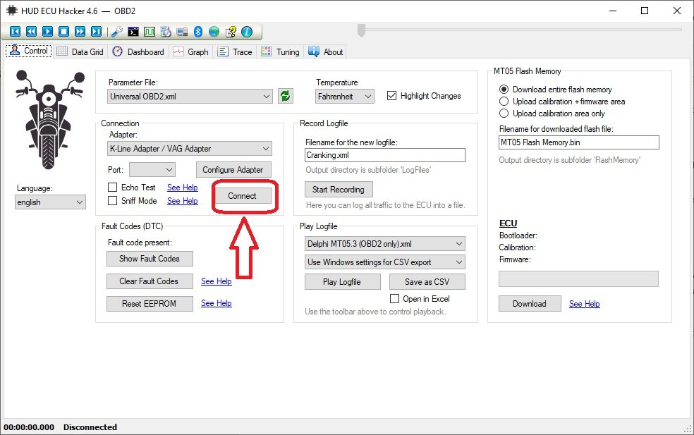
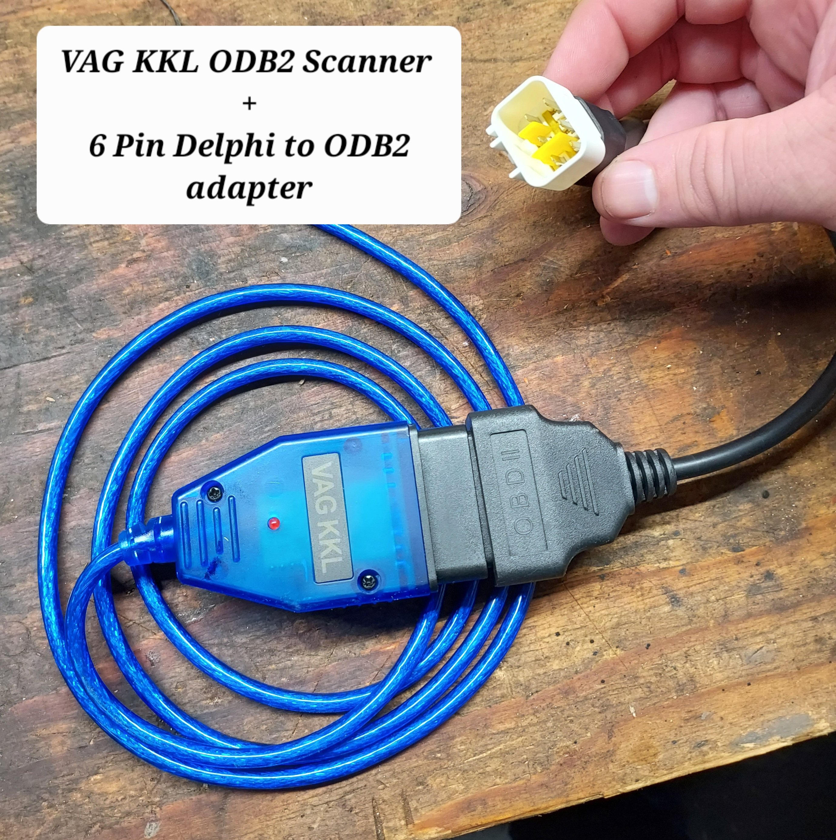
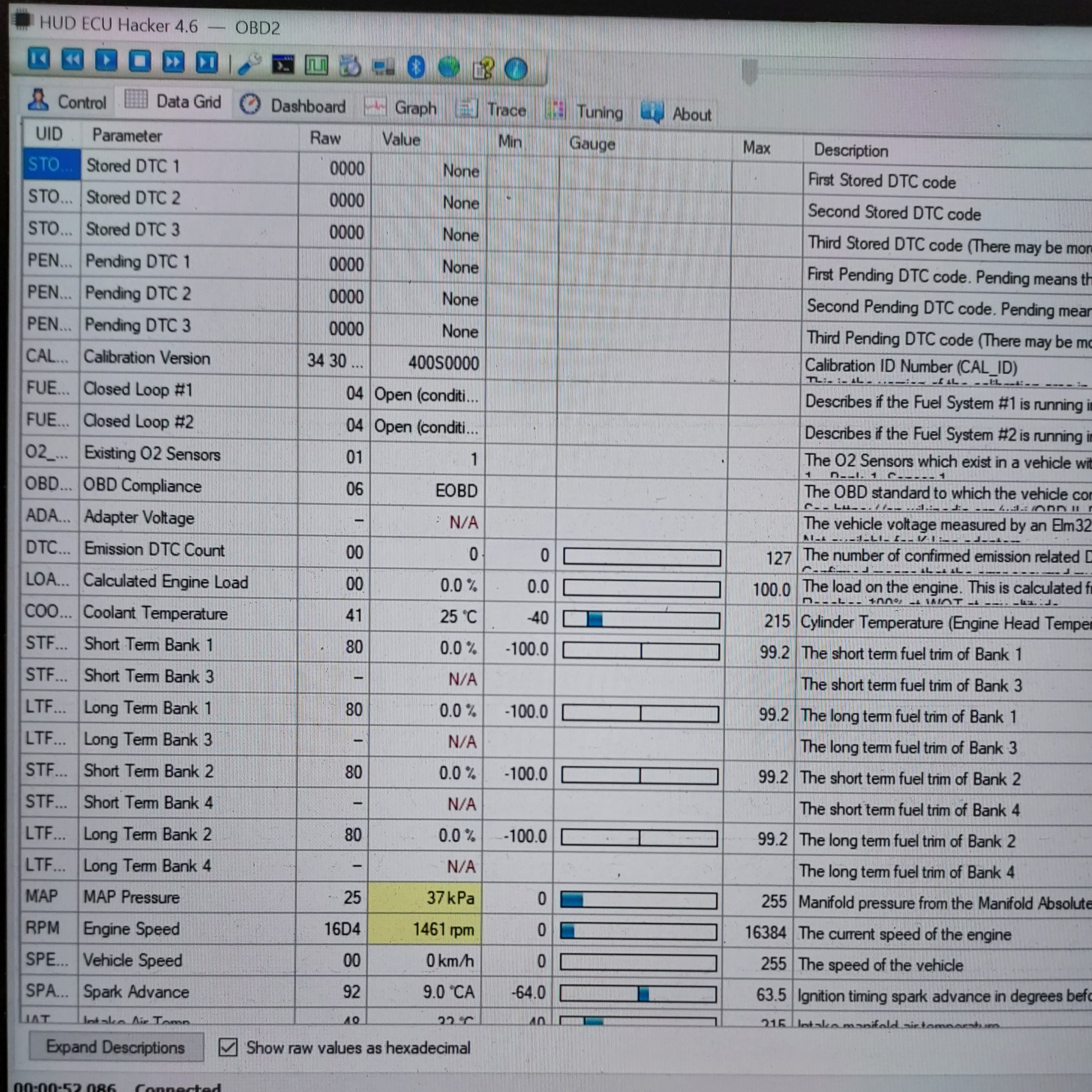
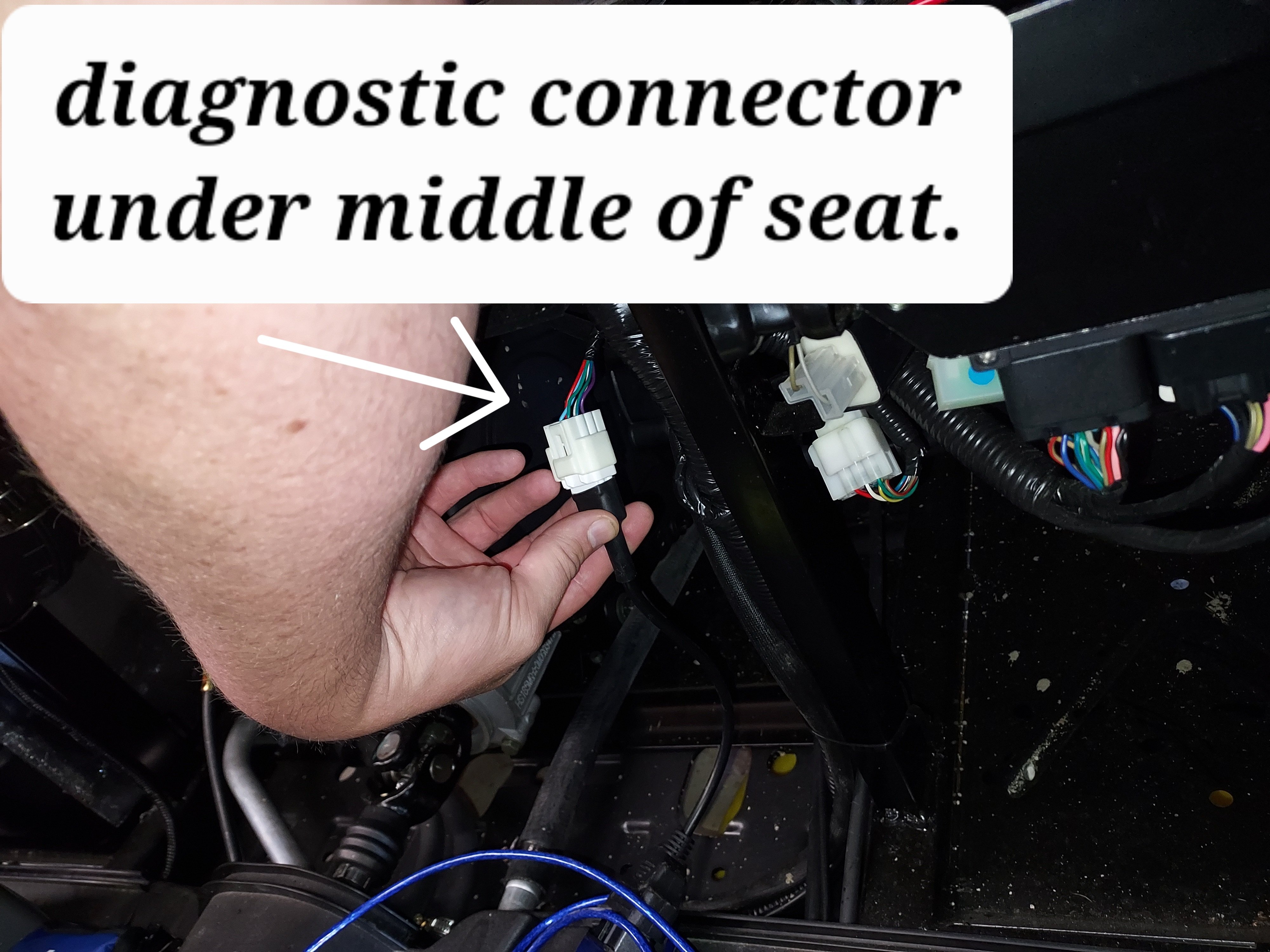
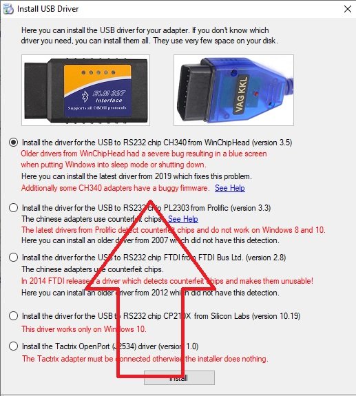
In order to connect with the ECU we need two cables. The first is a USB ODBII cable. HUD ECU Hacker’s documentation has a lot of different confusing options, but here’s what I went with and managed to get working, the cable is called “VAG KKL” it is a USB to ODB2 cable. It is available from a variety of sources for $10-15. The second thing we need is a “6 pin delphi to ODB2” adapter cable. It is also available for a similar price. In my case I ordered both from ebay, but there are other sources. Once we have our cable in hand we need to find the plug it in on your machine. My personal rig is a Coleman UT400, but the wire location should be similar for all Hisuns. My cable was located under the middle of the seat area. Just inboard of the battery, where the main wire harness split loom runs. The cable is a 6 pin (3x2) with a dust cap. Remove the dust cap and plug in the 6-pin end of the Delphi adapter cable. Note: When I was done, I left the 6-pin adapter connected, and zip tied it so it now runs to in front of the battery for easier access in the future. Next download and install HUD ECU HACKER DOWNLOAD Open HUD ECU Hacker on your PC It should prompt you to choose a driver to install. This particular cable uses the “CH340” driver (First choice on the menu) click to install, once installed hit the X in the corner to go back to the main page Once the driver is installed plug in the USB Cable, and plug the ODB2 end into the 6 pin adapter. The red led on the adapter should light up indicating it has power. Drop down and pick a com port on the main screen, it should show the VAG KKL adapter as a com port. Click connect on the main menu. It will pop up a bunch of fast scrolling text indicating it is connecting. Once connected you can click through the various tabs to see different data sets. The main menu also has the option to show fault codes, clear fault codes, reset the EPROM back to factory. The other function that may be helpful is recording a log file. You can record a log while operating the unit, and come back later and replay it to try to better diagnose what is happening. Within the various pages you will see the reading from each sensor. Sometimes a sensor reading will be off enough to cause running issues, but not enough for the ECU to realize its an issue. For example if the engine thinks it’s really warm, but its actually cold, it may not inject enough fuel to start. There are also more advanced functions, like adjusting fuel mapping, but that is beyond the scope of this tutorial. Full HUD ECU Hacker Documentation (Very technical reading) If you find this helpful give me a comment below or a thumbs up.
5 points
-
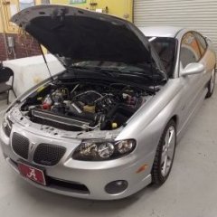
White smoke is usually coolant leaking into the cylinder. Sounds like a blown head gasket to me.4 points
-
Just wanted to give update . It was the ecm. Put new one on and got spark immediately to front cylinder. Ran but smoking and no power. I checked back cylinder and no fire. Pulled coil to check with meter and found wire was not getting good connection where it plugs into coil. All good now . She will scream !!!. Next is to figure out why 4x4 switch wont turn. Thanks for all the imput....4 points
-
Hello to anyone who reads this. I am Jon and I own J&M Outdoor Power, a very small, small engine repair shop. I was approached by Coleman about 6 months ago to become one of their Warranty Centers. I recently received 3 different UT400's and a UT500 all with similar issues. These units range from 2 months to 2 years old. Customers state that the unit(s) was/were running fine, then heard a pop and a loss of power, two would no longer start. The two that would run would not achieve normal operating speed (around 20mph I would say) without redlining the RPMs. I quickly found that the Valve lash on each unit had become too large on some(both intake and exhaust) and too tight on one(just intake). After setting the gaps to .005(I found multiple different people suggesting bigger and smaller gaps, but no definitive Coleman Spec number yet) every unit starts, runs, and achieves top speed without issue. I don't know how many others have come across these issues, and I wanted to get something out on the web for others in the same predicament. Please let me know if you have had similar issues. Edit: I realize that this will not be a fix all solution for this issue, as the oil level and condition should be verified before moving to the valves. Many times improper oil conditions will cause valve lash to change. These units all have good oil and proper oil changes.3 points
-
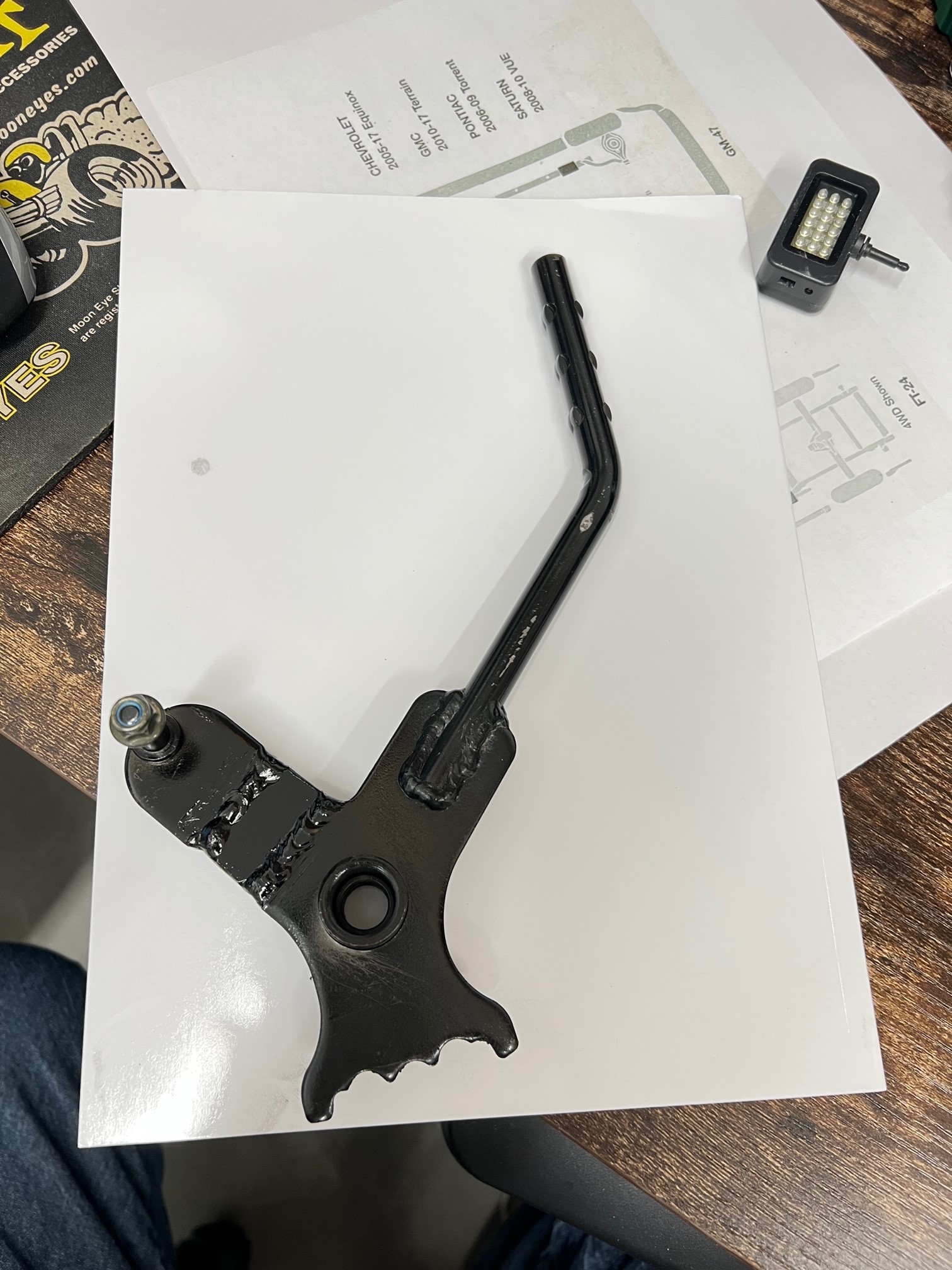
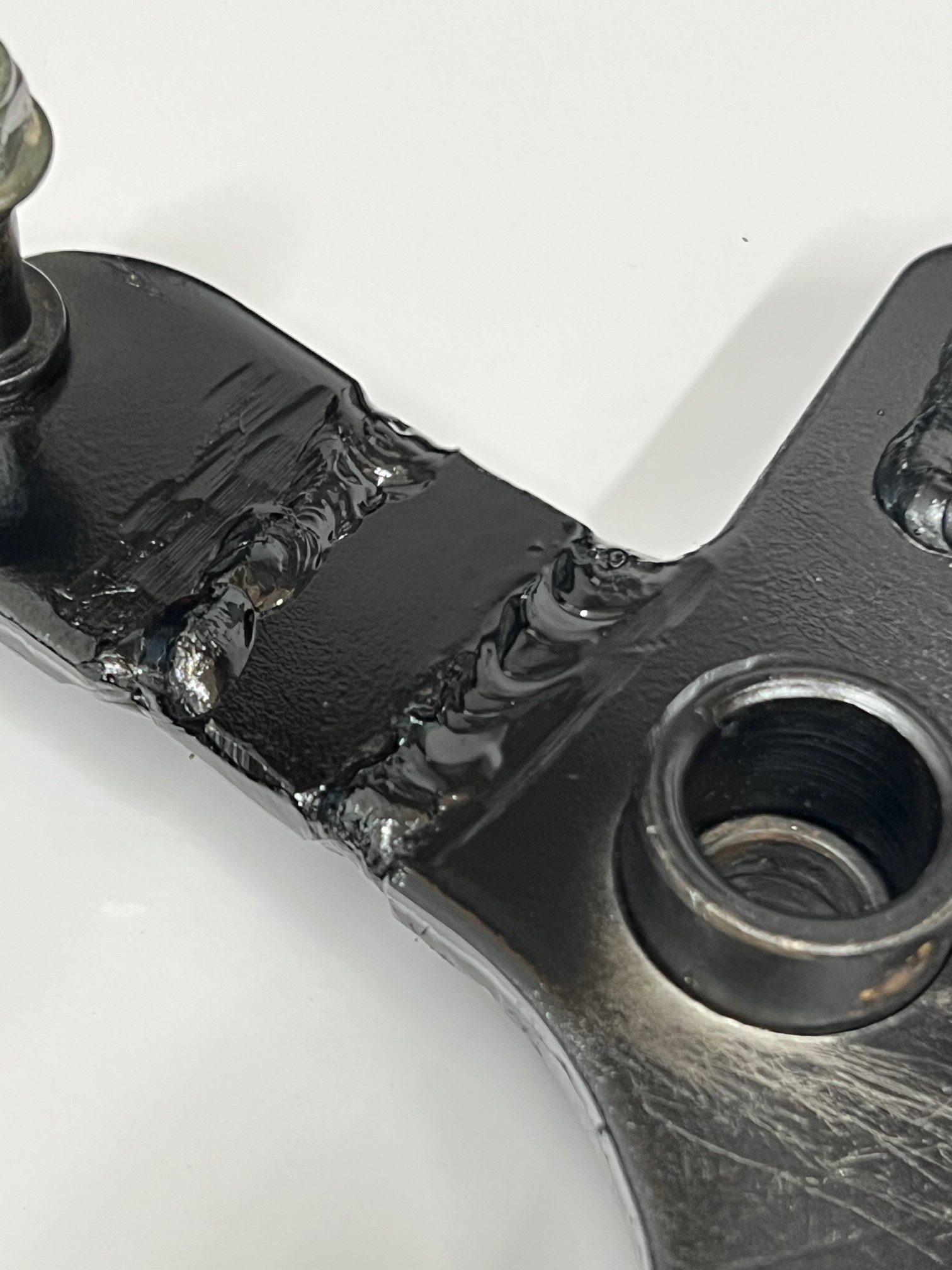
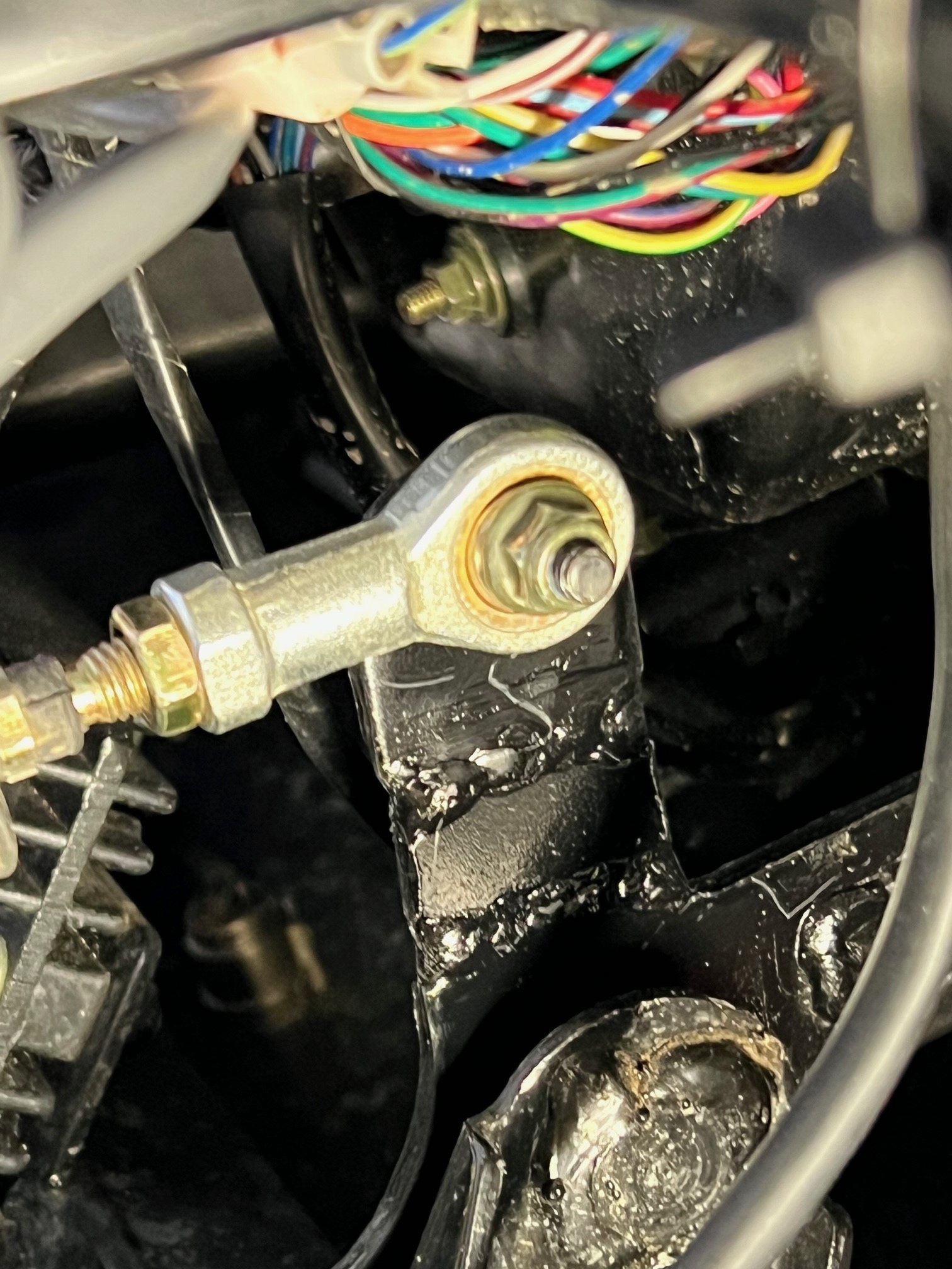
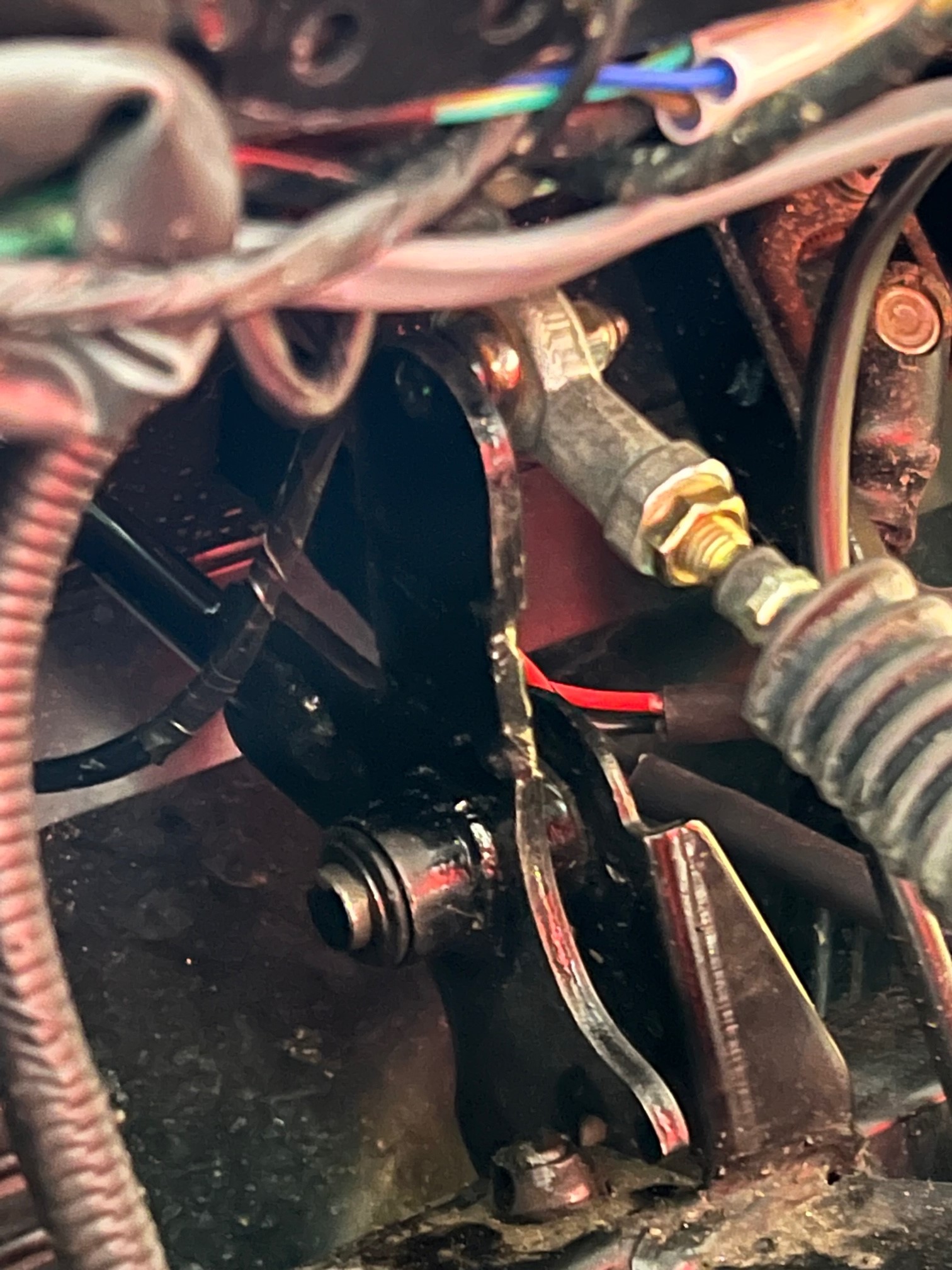
Hello again! I now have a pretty good running Coleman UT400 after a top end rebuild, wet clutch rebuild and a repaired crankcase... ! It plows snow great, but I was also having the jumping out of gear problem, mainly reverse, but a couple times out of forward. I would quickly place it in N and then let the engine idle down and shift again. This worked most of the time. I did some research and found that some have modified the shift linkage. The problem with just adjusting the shift cable is that it really NEEDS more throw, not an adjustment. From what I've read and viewed on the Internet, the linkage arm needs to be about 3/4" longer to gain more throw in both directions. On YouTube, the guy had to remove the shift linkage hole trim and notch the side of the dash to get the shift linkage off the pivot pin. BUT this is NOT necessary. When the "E" clip has been removed and you fish it out of the firewall somewhere, the shift lever is now loose. I had to pop the top of the shift knob off, remove the retaining screw and then heat the lower portion of the knob to get it to come off the lever. Once you have the shift lever loose, push it towards the right to slide it off the pivot shaft. But it won't come off just yet. Use a small pry bar/screw driver and slide the nylon flanged bushing out of the left side of the lever. This lets the lever slide off and get into a "loose" condition and it will twist and come right off without removing the dash trim, that could be a bugger to get back on correctly. Once the lever is off, press out the other bushing so when you're welding on the linkage arm, you don't melt the bushing. I found a piece of scrap metal the same thickness as the lever arm, just over 1/8" thick, close to 3/16". I cut my arm and beveled the edges for better welding. I added a piece just over 5/8" long and kept about a 1/16" gap between the arm and the new piece. Once welded on bother ends, it adds up to just about 3/4" or so. I reinstalled the lever after painting it and did an adjustment on the cable. By the way, it's easier to remove the cable from the bracket on the frame. This gives you more clearance to maneuver in that area with your hands. ALSO, you will need to get a 12" adjustable wrench and slide it over the cable mounting bracket and tweak, to the front, the steel so the cable is pointed upward a bit to now realign with the new longer shift arm lever. There's more than enough metal for the tweak and it will line up perfectly. I now bottom out the shifter on the transmission BEFORE I run out of throw on the shifter... I've tested it just a bit so far and it shifts much better with the longer throw. One of the Coleman authorized repair facilities said that he worked with Coleman to get a new part that's longer by 3/4". He's modified a few and it works perfectly for him. Just doing the cable will just short you on the other end. Here's some pictures of my modified shift lever etc.
3 points
-
I have come to the conclusion @Joe Toup must be one of the very best, most helpful members here!!! He has been tireless sharing his knowledge and expertise helping me solve a problem. I am sure I'm near a good solution thanks to Joe!!👍👍👍3 points
-
There are actually 5 disc brakes on these machines. 1 for each wheel and 1 on the rear driveshaft for the parking brake. I've read several complaints of the parking brake one being too tight from the factory so I would check the cable and make sure there's a little slack when the parking brake is released. If that is good I would jack up each corner Individually and spin the wheel to listen for noise and feel for dragging. That should help pinpoint where the issue is.3 points
-
anybody else getting spam /fraud private messages on here besides me? How do I report it? He calls himself Maria .under ORANGE 15 name.. wants to hook up in UTVs .. con artist in Pakistan probably.. Cant ADMIN block this crap ? geesh3 points
-
Just looked at the Lowes add for that, pretty much looks like an MSU 500/700 that Hisun made for Massimo back then. Take a good look at the badging on parts to see who it's actually made by, my guess is it's still Hisun.3 points
-
Its my 2nd day on this plat form. I'm new here in this community but in these two days I got some Premium recommendations. I was in search of these recommendations form the past few months. Thanks you so much for creating such kind of the community. Regards: Zeeshan Mehmood3 points
-
Put 15 miles on it today mostly on the beach in 4WD--the front diiferential is definitely smoother and quieter, and engaging/disengaging 4WD and front lock more positively with the ATF...3 points
-
So how can i fix my UTV? " we'll circle back"3 points
-
For a 16 digit PIN/VIN, the 9th number indicates the year. Hence, in this case, the OP's RTV is a 2006. Which is the same year as y RTV:
3 points
-
3 points
-
Waiting for snow.....
3 points
-
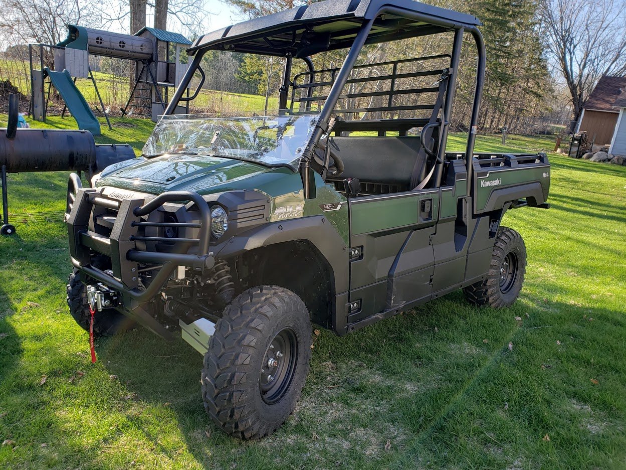
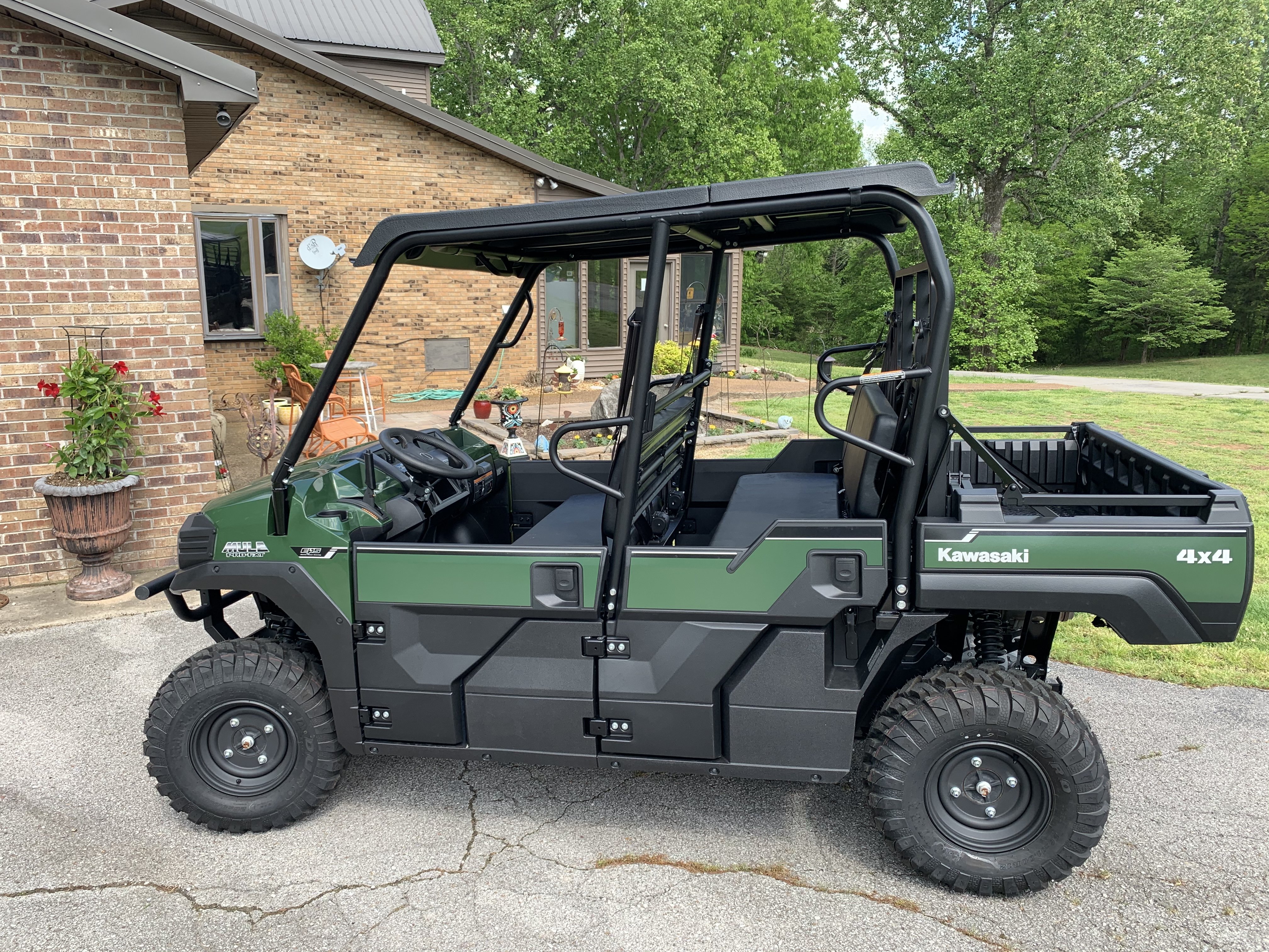
Finally delivered today!!
3 points
-
Got it home!
3 points
-
They got ours delivered today (instead of tomorrow).
3 points
-
My dealer just got parts this morning (purchased on Jan. 20th) - I should have it by the weekend!3 points
-
Are you talking about an electric heater? if yes its likely too much current. There might be 10 amps of available current coming out of the rectifier that isn't already claimed by the ECU and factory lights. 10 amps @ 12V = 120 Watts, which is about what an electric heating pad runs. If you're talking about a fan for a engine coolant based heater it's probably ok. If you have accessories and the running voltage is below 13.5V you have too much stuff attached. If the battery light comes on it means the battery is actively being discharged while running. Stator based charging systems on these things and tractors etc are really meant to power the ECU and factory systems not to provide a lot of extra power for other stuff, it's not like the alternator on a car.2 points
-
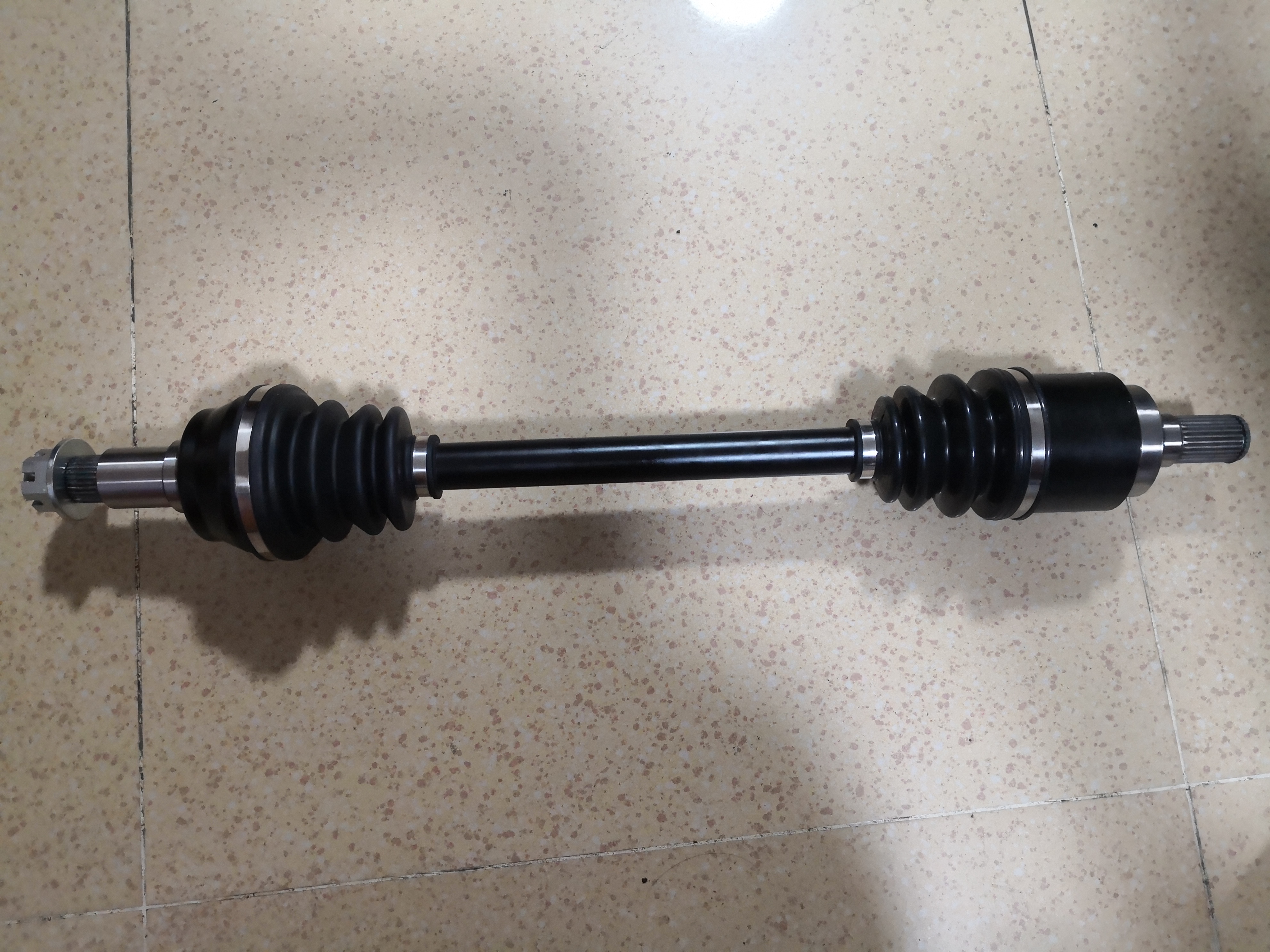
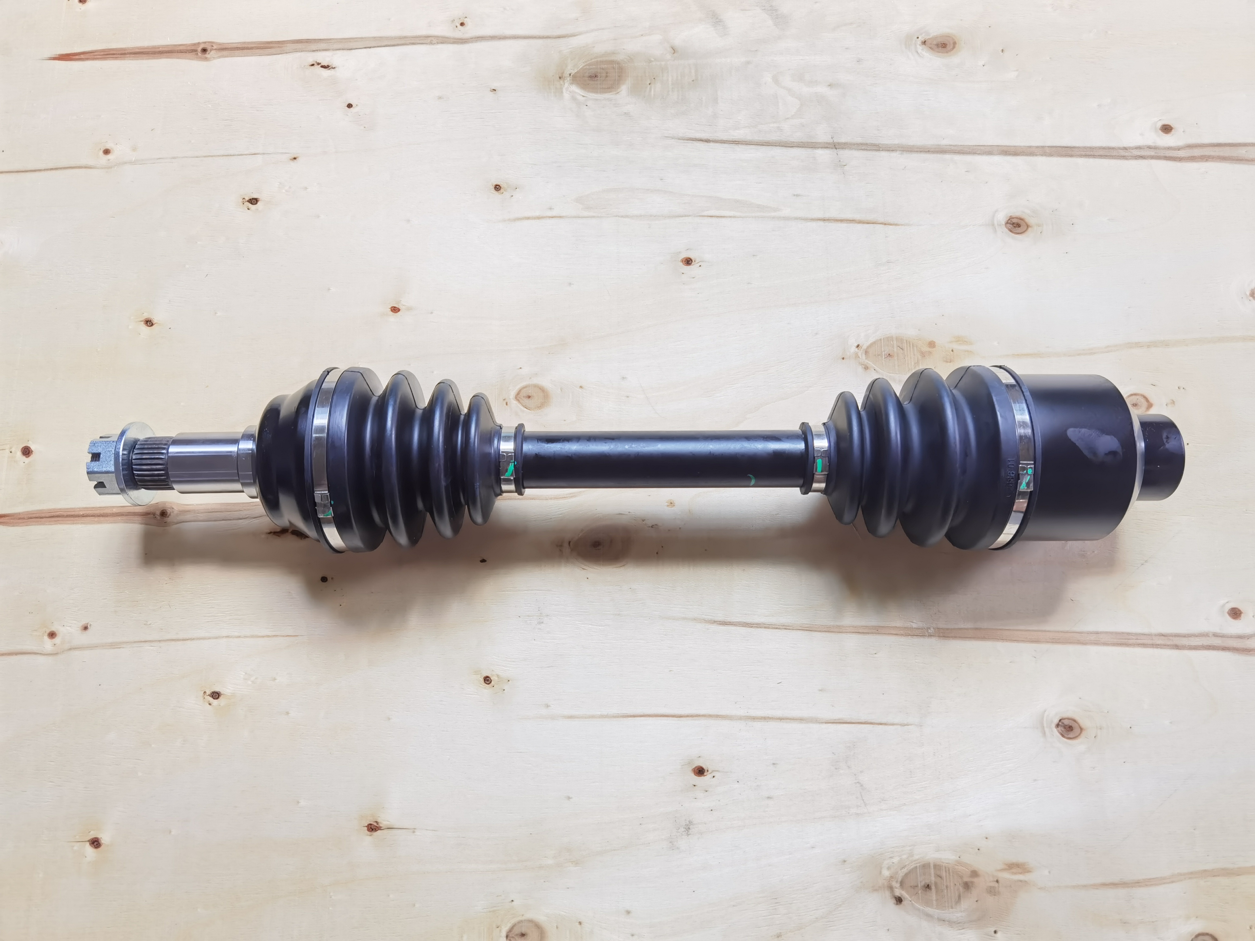
Hello Everyone Brand new Joyner CV AXLES are waiting to be unloaded at LA port and then be sent to warehouses in Charleston, TN , BALTIMORE, MD and Groveport, OH. Estimate they will be available for shipments to end customers in about 2-3 weeks. These CV AXLES are ordered in February this year and now it is middle July. Very long time to get these parts. Qty for each model is not big. Detail as below: S/N Part No. Description Charleston, TN BALTIMORE, MD Groveport, OH Total 1 D650.03.02.02.00 650 Sand Spider Rear left 3 2 3 8 2 S650.03.02.02.00 650 Commando Rear 7 6 10 23 3 TR1100.03.01.03.00 TR1100 Front 3 3 4 10 4 D650.03.02.03.00 650 Sand Spider Rear Right 3 2 4 9 5 S800.03.02.02.00-R2 800 R2/4 Rear Shaft 4 4 6 14 6 TR1100.03.02.03.00 TR1100 Rear 6 5 9 20 7 S650.03.01.02.00 650 Commando Front Left 3 3 4 10 8 S650.03.01.03.00 650 Commando Front Right 3 3 4 10 Below items are also available. These items can be shipped in days CAGE: 1. 800 Renegade R2/R4 Front outer cage --- 5 pieces 2. 800 Viper SV1100 Drive shaft rear Left outer cage --- 5 pieces 3. 800 Viper SV1100 Drive shaft rear left inner cage --- 3 pieces CV BOOT: 1. 650 Commando Left Front / 650 Commando Right Front /650 Sand Spider Rear Left / 650 Sand Spider Rear right / OUT CAGE 2 pieces 2. 650 Commando Rear OUT CAGE 1 pieces 3 Trooper Front / Trooper Rear / 800 R2 R4 Rear OUT CAGE 2 pieces 4 650 Commando Left Front / 650 Commando Right Front INNER CAGE 1 pieces 5 650 Sand Spider Rear Left / 650 Sand Spider Rear right INNER CAGE 1 pieces 6 650 Commando Rear INNER CAGE 1 pieces 7 Trooper Front / Trooper Rear / 800 R2 R4 Rear OUT CAGE INNER CAGE 2 pieces Anyone who need above items please contact me at [email protected]. Thanks. Other Joyner items needed, you can also contact me and I will try to help. Have good day Casey / Leaf Asia 2021-07-20
2 points
-
my Hisun in my Massimo , sold by Tractor Supply, assembled in Dallas, say Made In China on every part of all of it .. Altho it now has multiple Yamaha parts mixed in. lol2 points
-
Problem was using cheap eBay injector. Bought quality one and hot pipes went away. Running like new.2 points
-
Massimo MSU500 won't shift to low I would check the shift linkage. Adjust it make it a little longer, if it is not long enough it won't shift to low2 points
-
The P.S. has me thinking......you mention "Fuel mist" out of the valve rocker cover. All you should is basically NOTHING at crank speed. Any vapors blown out are from blow by (past the rings) into the crankcase. IF you are OVER FUELING and wetting down the cylinder walls (that is, washing off the oil coating) you will have blow by. Oil coating helps seal the rings. That is why an engine that has set (dried out) and low compression is given a shot of WD-40 or any light oil to seal the rings. This leads to the next thought.....If over fueling, the raw gas will "drain" into the crankcase and dilute the motor oil. Check motor oil level.....too high?....too thin?.....wipe on tissue and sniff the oil....Gassy smell?....will light off with a burn test (soak up some oil on a paper towel and see how fast it starts to burn). Oil basically won't. Diesel will start slowly but take off. Gassy oil....if you value the hair on body parts...hold at a distance with long needle pliers!!!! Gassy diluted motor oil will add to the fuel/air mixture via the breather tube. Similar to a turbo seal failure on a diesel......RUNAWAY even after the injector pump shut down...very bad ending! Drain oil and replace filter....won't get it all (always some oil remains that cannot drain) but will dilute the gas. BONUS: Pulling the vent tube will clean up a mystery RICH run be it carb or FI (everything is correct BUT) after the motor warms up and cooks off the gasoline----sorta like an EGR Evap system. Slop fuel never lights off or barely runs depending on the degree of "slop". You state pulling the injector, the engine runs until it runs out of fuel. ARE you leaving the injector hole OPEN. This will allow lots of fresh air into the cylinder and will light off a rich mixture and then die because no more fuel is injected. ASSUME the ECM is sending the correct pulse width to the injector for now. Injector can hang and "piss" instead of spray. The key is the 14.7/1 air fuel mixture. Too RICH.....runs heavy and then dies at idle. May start to run, but as the leftover UNburned charge gets richer-----labors-----pukes. Too Lean......no start....fuel is there but cannot lite off.....then as it builds up, you get a pop only to be to lean again.....repeats the cycle.....THIS IS HELL ON THE STARTER AND REDUCTION GEARS. This also load the oil with gasoline (unburned). Again the fuel correct, look for a restriction in the air intake (not enough air).....common causes....CRITTERS...mouse house....full of acorns....rag pulled in for a nest, and so on. EASY TEST: Remove the air intake plumbing at the throttle body. Plenty of air now. If runs, check out the air box/plumbing. IF NO RUN....next section. Too much fuel: Time to test the ECM/injector system. ANY BAD input signal to the ECM will make the fuel delivery too much or too little. Pull spark plug. Read the insulator tip color. Just right is a light TAN color. Very WHITE...blistered LEAN. RICH has a BLACK, SOOTY, shiny black/wet black (carbon is fuel soaked). If really black, they might fire outside to the engine block BUT "blowout" under compression even at idle. If not too bad, they might run at idle but when sputter and die when a heavy demand on the ignition system (acceleration) is applied....drop in a new plug for testing to just to reduce the possible list of problems. Pull the connector to the fuel pump (under the pass seat). This is the fuel pump power (from ECM) and fuel level signal. No guessing if you found the right fuse/relay. This will stop the fuel delivery (40 PSI) to injector. Injector will still get pulses. You will shoot a short burst of starter fluid into the air box (plumbing reattached and filter OK). The motor should lite off and run until it is out of fuel. Repeat. Repeat. If works every time, give a double burst when running to "sustain" the run. Repeat. If this works, you have the ECM/input signals to ponder. This gets deep for most. Coolant temp sensor....open circuit RICH. Thinks it is at the SOUTH POLE -40 C. Like a choke for carb. Throttle position sensor.....wrong fuel mix to match the air thru the butterfly valve. MAP sensor/ambient air temp....measures engine load....wrong signal rich and lean. O2 sensor....signal to tell if RICH or LEAN. Has heater circuit to get it up to operating temp. Heaters open (toaster that does not toast). Throw in smashed wires, critters that live the taste of plastic insulation on wires, stick run thru harness, heater shorted to SHARP edged heat shield above the exhaust. More common failures are the MAP/IAT (intake air parameters) and O2 sensor. You got a lot of checks to get down to where the problem is. BTW, the ECM is a DELPHI MT05 small engine unit capable of a twin (2 inputs for the two cylinders individual O2 sensors). Check out web page for specs, pin outs for both the Grey and Black connector (PDF format)....magnitudes better than the "manual" supplied when first built. Only covers the electrical engine management with a generic diagram of the analog input(s) and the outputs like fuel pump, ign coil, etc CHOW.2 points
-
after all the complaints on this forum about the other brands of utv's, i will stick with my mule...........not the fastest, not the most powerful, but it hauls stuff around the house and plows snow just fine..........2 points
-
The real problem, as I see it, is that the codes given are consistent with an engine that's running poorly. So imho, if it's not running with a substantial miss, then something else is going on. Like a possible failure of the CPU. Manufacturers are typically reluctant to give away parts without a reliable, trusted diagnosis of failure, such as that provided by an authorized service center. And a new CPU could be quite expensive, with no guarantee that'll cure the problem. Throwing parts at it is never a good plan anyway. Fixing it yourself, could be a long, expensive, frustrating endeavor. Complete with long down times, and fairly involved diagnostic procedures. If it were me, I'd try to make it Lowe's problem. By any means necessary, including a return.2 points
-
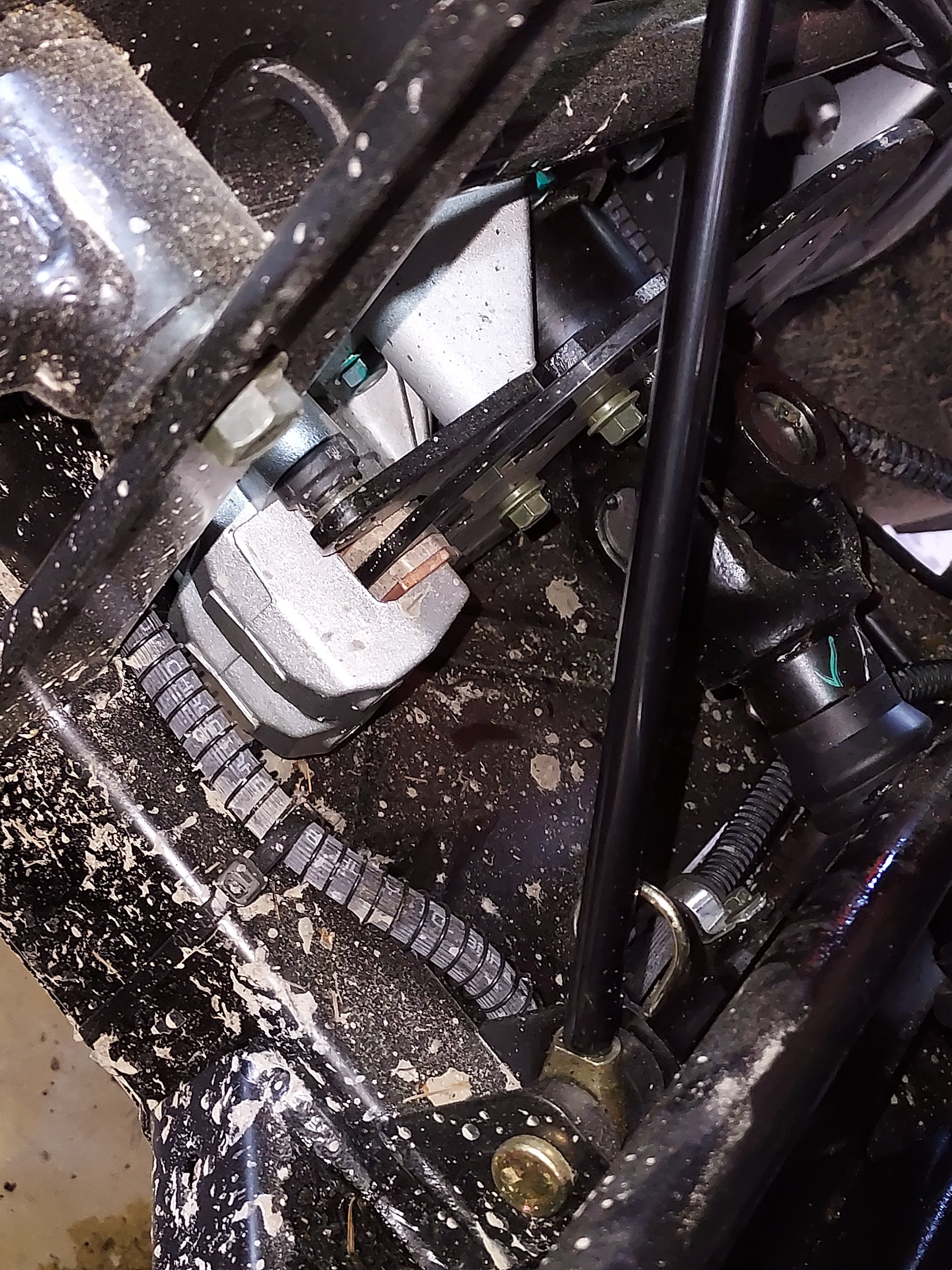
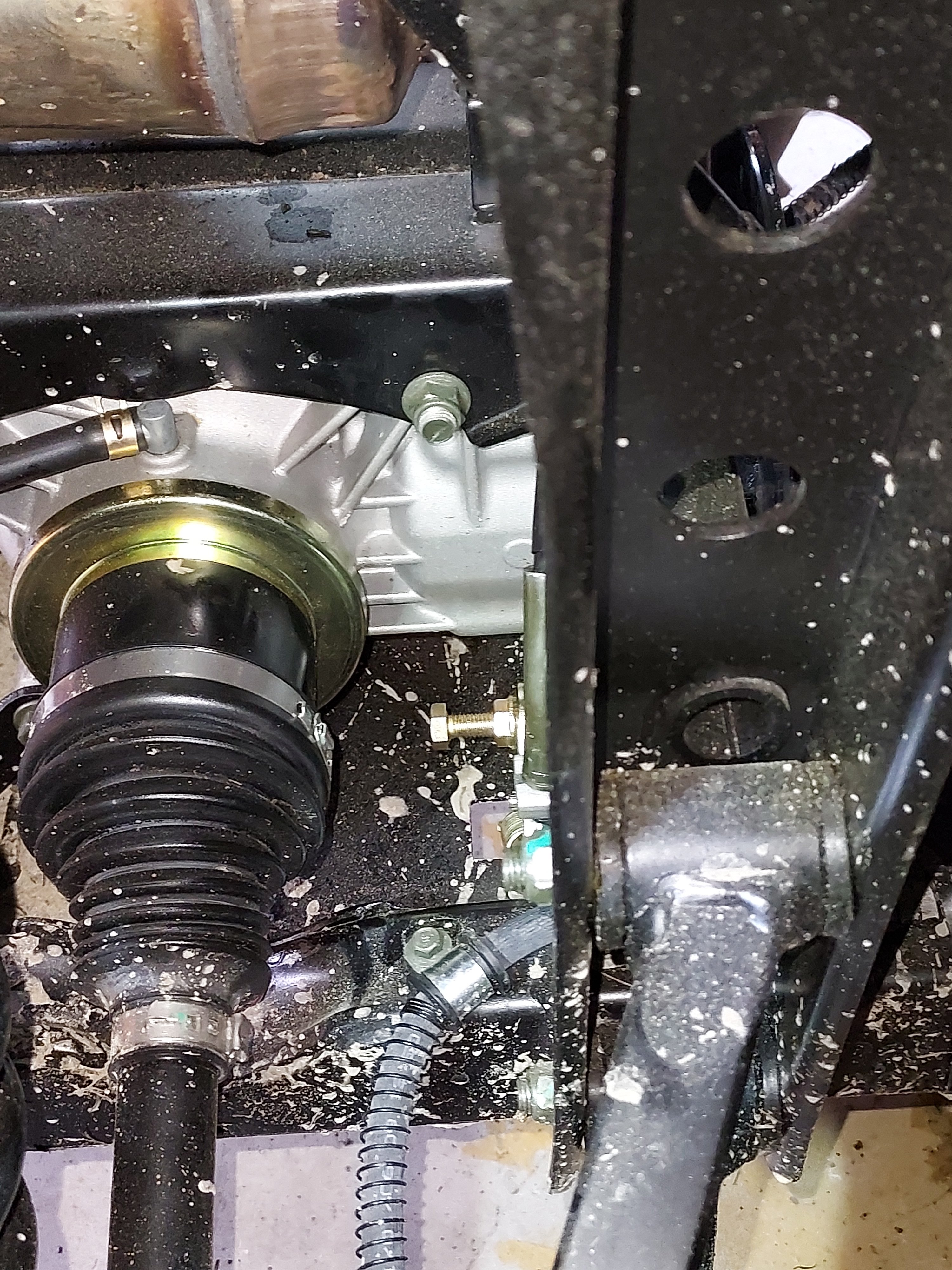
I was under the rig playing today so I decided to adjust the parking brake just to make sure it was ok, since I've read a couple people having them adjusted too tight from the factory. First picture is the parking brake disc & caliper from the passenger side. Second picture is the adjustment bolt. How it works: it's a cable operated disc brake with a locking pawl to hold it where you push the pedal to. Procedure: The pad tightness is adjusted by moving the bolt in the 2nd picture in and out. When you tighten it it pushes the pads together. The extra nut on it is a lock nut. Using a 13mm wrench loosen the lock nut. Back it off about halfway just so it's out of the way. Next tighten the bolt by hand until it stops. From there back it off about a half turn. Push the parking brake and make sure the pedal "locks up" before running out of travel. If it doesn't adjust the bolt slightly tighter and try it again. Once you're happy with the adjustment tighten the lock nut while keeping the bolt stationary.
2 points
-
LOL!2 points
-
Yep, much better for hauling stands and everything else. Although it's a little harder to load a big buck in the dump bed than it was to drag one across the atv. I picked up a chain-on hoist after last season! https://www.amazon.com/Viking-Solutions-VS-VHK001-Game-Processing/dp/B00KTMXNTY/ref=sr_1_6?crid=1YOHK2JY2Q450&keywords=hoist+game&qid=1652957591&sprefix=hoist+game%2Caps%2C155&sr=8-62 points
-
well, blame unions and democrats for making labor costs of $60 /hr for a guy pushing a button on a robot .. If that belt was Union made in NY or CA it would be $300.00 I have found GATES to still be good quality belts even tho its imported.. Dont buy the EL CHEAPO brand at Autozone.. I did once because Gates was out of stock.. lasted 2 months . Luckily I had put the old belt in the trunk.2 points
-
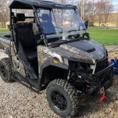
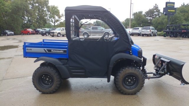
Finally found a pic of the OEM Kawasaki cab enclosure on an SX XC. Looks tight and I think the price tag is warranted so this is what I'll be getting for next winter.
2 points
-
Kinda concerned that he hasn't chimed in yet 😉2 points
-
Have the head and block mating surfaces checked. Sure sounds like a warped head or maybe a crack between the cooland and oil passages. Common occurrance when overheted and run until it runs no more. If warped, might be able to have the head and/or block machined. A crack can also be repaired (maybe).2 points
-
It's still under Kawasaki's Three year warranty. let the dealer look at, no need to risk voiding your warranty by messing with it, as dealerships can be picky about that. i always advise people, if it's under warranty, and there is an issue. let the dealer look at it. and fix it.2 points
-
you have air trapped in the head. try bleeding out air at head and at waterpump ....or .you have a bad head gasket .. Hisuns are not for riding, they are for working on2 points
-
Okay I think I figured it out, apparently that piece should have stayed on the engine and not came off with the oil filter, so I have installed back on the engine and then put the oil filter on had a momentary brain freeze.2 points
-
Your probably picking up the heat that the Radiator Fan is throwing at the dash. There is a guy in Mississippi that makes a Radiator deflector shield that mounts to the back of the Radiator and deflects the heat down to the ground. I installed one on my machine and it does help a lot with the heat. The shield is also hinged so that in the winter time you can lift up on the door and now you have the heat coming back to the firewall to help with warmth in the cab. The only thing I can’t tell you yet is how much dust is the shield going to kick up while on the trail. I’m scheduled for another trip to the Hatfield And McCoy trails in October and will find out then.2 points
-
Hey there - There are tons of aftermarket accessory shops for your 800SX; UTVsource , sidebysidestuff , countrycat , theutvsuperstore and my personal favorite, Ebay... Amazon has some items as well. Just do a google search on 800SX accessories and go nuts. I have installed about every upgrade option you can possibly add on my 800SX TTE (other than hard doors or snow plows) and above is where I purchased 90% of my stuff. I do recommend a folding front windshield if you trailer or drive in the hot summer as it's a welcome relief to have a breeze on really hot days. There is quite a bit of heat that come through the seat & floorboards from the engine and even that can be drastically reduced if you add heat shielding from like DEI powersports... Really like the factory under seat storage as it keeps lots of gear organized, separated and sealed tight away from critters & moisture. A curved light bar across the top will light up your world as well. .. I will caution folks though if you add a factory heater... The $900+ factory heater is a HUGE pain to install (literally takes 20+ hours) because of the 4 separate plastic 90degree elbows you have to independently align in mounting at the firewall. You get one aligned and then next one pops it off. You finally get 2 aligned, the third pops of 1 or both of the 1st two and so on and so on and so on.... It takes hours, lots of increasing cussing and infinite perseverance to finally get all 4 aligned and THEN you have to carefully ratchet the whole thing up to the firewall without popping one of the 4 off. A couple buddies (Ration your beer proportionately as it's going to take a while), Gorilla/Duct tape will help to hold them in place but again, it still takes hours. I curse the designer of this for making the elbows hard plastic vs flexible rubber as that would make all the difference! After you mount the heatercore/blower unit, you will also find 2 of the 4 duct housings in the kit are too short to reach the dash vent outlets so - plan on improvising in advance or cutting a 2 foot section out of your shop vac to lengthen both a foot. The heater integrates nicely once installed & they work very well but the blower is also really noisy on med or high... Hard to talk over noisy... If I had to do it over again, I would have soundproofed the blower housing a bit before install. I believe an aftermarket Inferno heater would work just as well and install in a fraction of the time for half the cost... Just my 2 cents! I'd post pics but don't see the option on the menu... Thanks and enjoy!
2 points
-
BINGO!--I read this in your first post " has a lift on it " and thought to myself--well there you go... Contrary to popular web-based "fast &furious" opinion, and every now & then, the engineers that design this stuff actually do know what they are doing.2 points
-
My maternal grandfather (a Scotsman ME) always told us that "...the last time any machine started and ran properly may well have been the last time it will start and run properly." Also, "God created men and they are imperfect--men created machinery, so guess what that makes machines."2 points
-
I am lookin for recommendations. I would like to put a winch on my 2019 Honda Pioneer 1000-5. I have been looking at the Warn Axon 55s but would entertain any feedback from people regarding this or other winches.2 points
-
That's the whole point of having it pinned. I haven't looked for it here, but on other forums. When you open the sub forum for that make, it'll be at the top. No matter how many posts happen. It'll always be there at the top. So you can easily reference it anytime you like, by opening the Massimo sub forum.2 points
-
Ebay 4x137 is the lug pattern 110mm center bore. Sent from my moto g(7) power using Tapatalk2 points
-
My recall parts are at my dealer hope to pick it up tomorrow or Monday
2 points
-
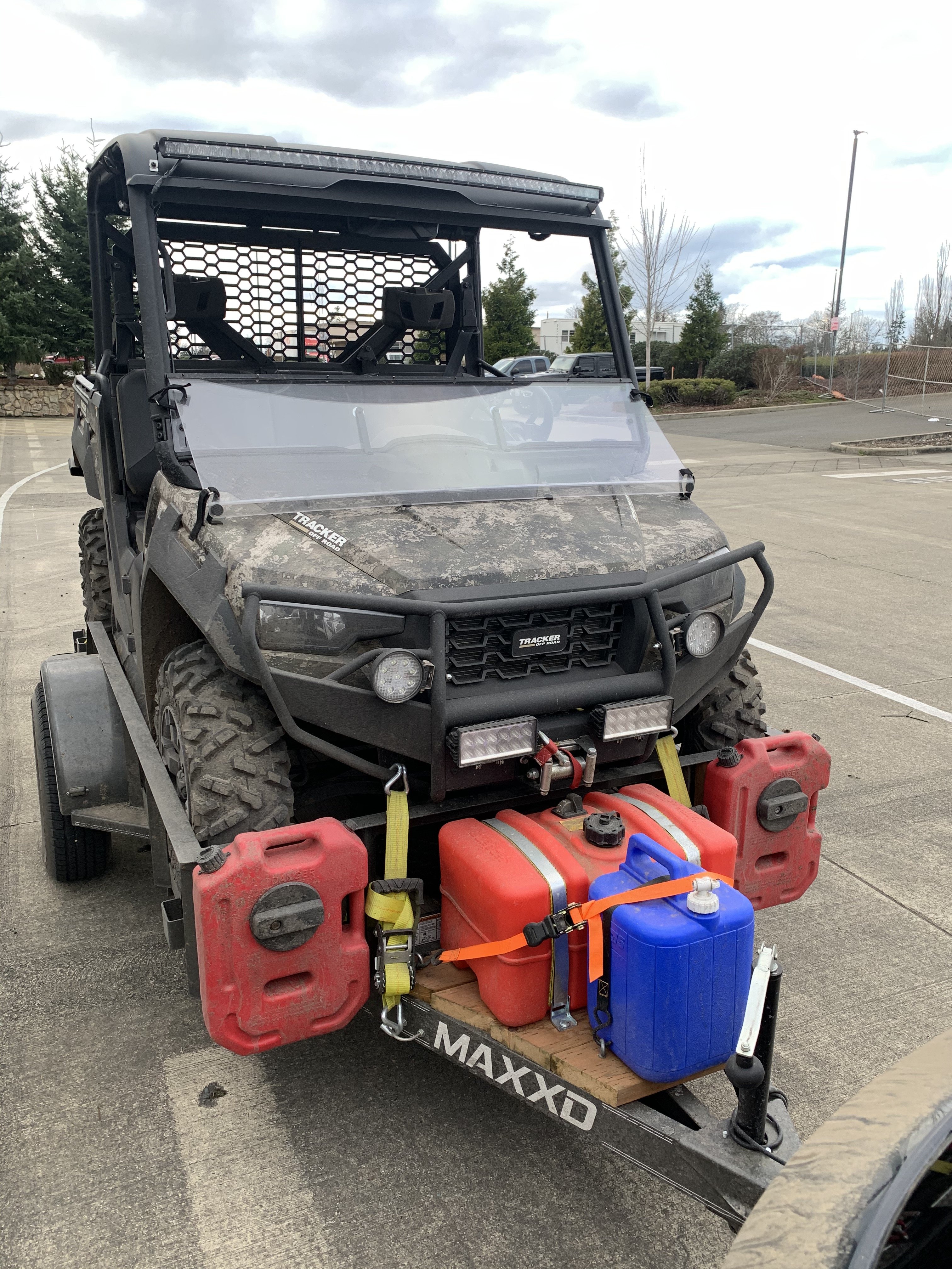
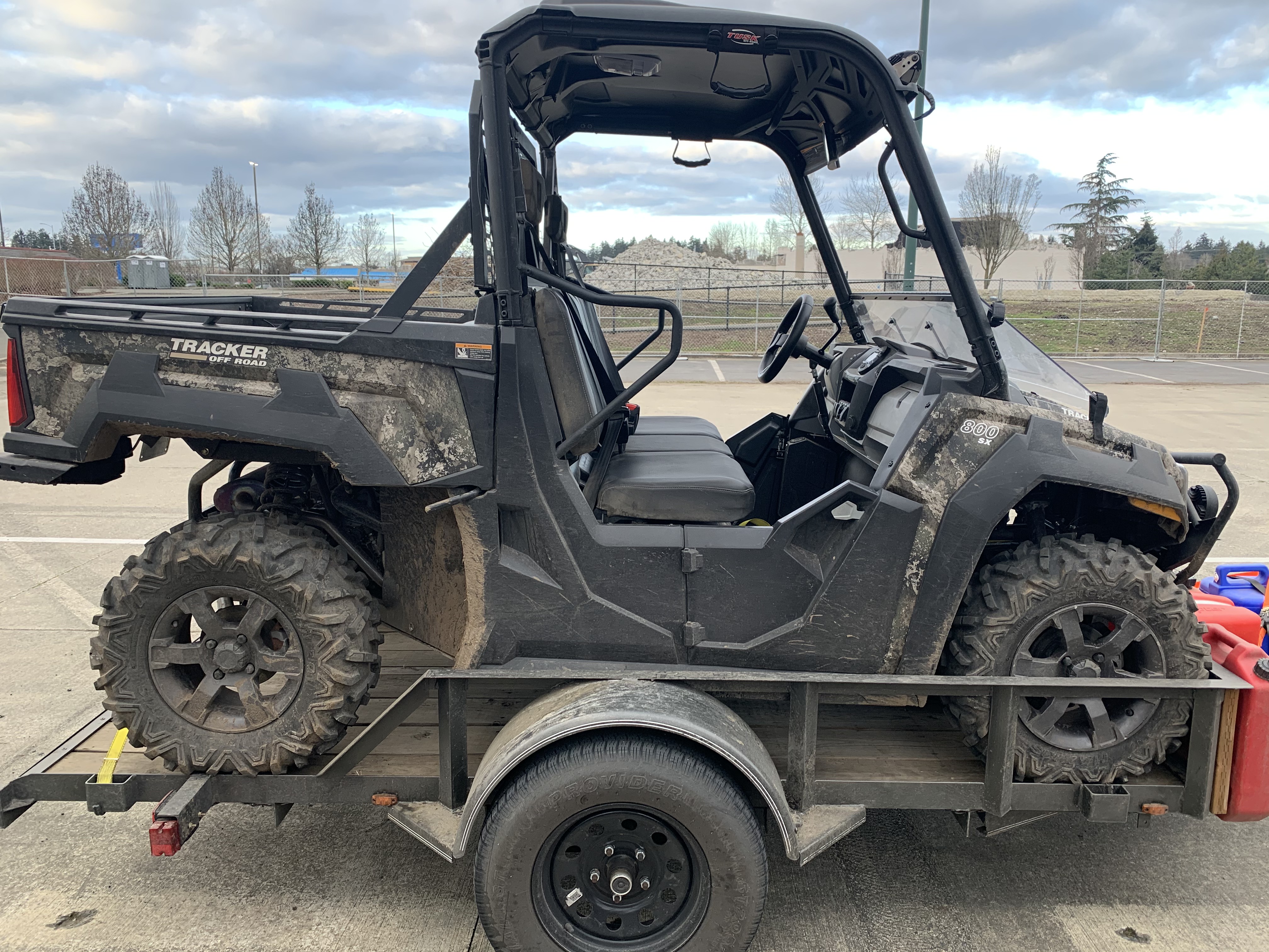
Picked mine up Friday, worked on the ranch all day Saturday and Sunday, love it, worth the wait. Ordered Jan 15. Front cab warm at the feet with the heat from the radiator, still cool here so no complaints, but come summer will have to get the Hood Scoop from Rockin' R Customs. Went with the over sized springs, What a nice ride, easy on the old back.
2 points
-
The back plate of the hub brake drum will interfere also if its bent out of alignment. I had to adjust mine after some repairs with a mallet.2 points
-
Also, you don't want dielectric grease on the metal contacts themselves. You want it around the seal of the plug, not on the contacts. The grease itself is an insulator.2 points


.jpeg.c11e7081f0d706ef84dc1e66677d68d4.jpeg)


This leaderboard is set to New York/GMT-04:00
